
Install Instructions


4
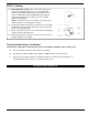
• Connect the red wire to the hot side (Terminal “R”)
of the (24V) transformer on the boiler.
• Connect the white wire to the neutral side (Terminal
“C”) of the (24V) transformer on the boiler.
• Connect one yellow wire to Terminal “R”.
• Connect the other yellow wire in series with all other
limit and operating controls.
STEP 2 - Electrical Wiring Options
• To prevent electrical shock , turn off the electrical power before making electrical connections.
• This low water cut-off must be installed in series with all other limit and operating controls installed on
the boiler. After installation, check for proper operation of all of the limit and operating controls, before
leaving the site.
Failure to follow this warning could cause property damage, personal injury or death.
WARNING
I M P O RTA N T: Boiler manu facturer schematics should always be fo l l owe d . In the event the boiler manu fa c t u r e r ' s
schematic does not exist or is not available from the boiler manufacturer, refer to the schematics provided in
this document.
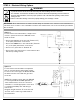
Option 1
For hot water boilers which utilize a simple series
circuit to operate the boiler, the RB-24E can be
wired as shown.
NOTE: The example shows wiring an RB-24E
to a Honeywell Model L8148E aquastat. For
other manufacturers, refer to the electrical
schematic to confirm appropriate connections
for obtaining 24 VAC power and wiring in
limit circuit.
Diagram at right assumes "Z" is the hot side
and "TV" is the neutral or grounded side of
the transformer.
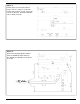
Option 2
For hot water boilers that utilize an aquastat
r e l ay to control the bu rner and circulator circuits.
To wire a boiler of this type, the Model RB-24E
should be wired in series with the gas valve
as shown.