
Installation guide


McAfee® Network Security Platform 6.0
Verifying the failover configuration
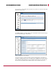
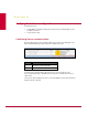
From within the CLI, you can instead run the command from either Sensor. The output
includes the failover Enabled and Peer Status fields. The former indicates whether the
Sensor at hand has been configured to be part of a failover pair, and the latter shows the
current state of the communication between the two Sensors:
Figure 21: show failover-status
In Figure show failover-status, the Sensor is part of a failover pair, and the pair is successfully
communicating over the heartbeat connection.
Testing failover setup
Once communication between the Sensors has been confirmed, the failover configuration
should be tested.
The way in which the configuration is best validated will vary from setup to setup, but these
tests should be similar to the ones performed after the Sensors were physically installed
on the network.
The key differences this time include the following:
• In the specific case in which the network at hand has two active paths that route
asymmetrically, the intrusion tests that previously failed should now be successful
because both Sensors are analyzing all packets from all flows.
• Existing session state should not be lost when a Sensor goes offline.
The most precise way to confirm that the session remained intact after the “failure” is to
capture and analyze packets. A more rudimentary test is to open a browser and start a
large download while one Sensor is taken offline. If the state is successfully kept, there will
be no fatal interruption in the download process.
If the state is lost, confirm that the Sensors are indeed communicating with each other.
If the Sensors are not communicating, try the following steps in the order shown:
31