
Installation guide


McAfee® Network Security Platform 6.0
Defining the Network Security Platform Failover Pair
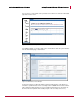
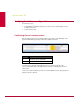
Once complete, the display of the user interface will change to reflect the existence of the
new failover pair:
Figure 16: Update configuration
A new failover pair node now exists in the resource tree (left pane) in Figure Failover Pair
administration. That node contains icons for each interface taking part in the failover
process. Also within the failover pair node is a list of its member Sensors.
Most configuration options are hereafter done at the failover pair node level. For example,
you can now apply a policy, update the configuration, or even create an ACL rule at the
failover pair node level and it will automatically propagate to each of the member Sensors.
On the other hand, you still configure the port settings, view interface statistics, and
upgrade the Sensor software at the Sensor node level. So the easiest way to get a feel for
the failover pair configuration process is to examine the user interface once the pair has
been created.
Note: The Sensors must be running the same software version to run in a failover
configuration. However, you upgrade software at a Sensor level, even those that are
part of a failover pair. The recommended upgrade procedure is to therefore upgrade
the software version on both Sensors, and then reboot them sequentially. That is,
once the upgrade process is complete on both, reboot the first, confirm that it has
rebooted without error, and reboot the second.
23