
Installation guide


59
Adding Physical Interfaces for Master Engines
5. Click OK. The Physical Interface is added to the interface list.
6. Repeat from Step 2 to add any other Physical Interfaces.
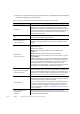
Virtual Engine Interface ID
Select the Interface ID of the Physical Interface in the Virtual IPS
engine that is associated with this interface.
Second Interface ID
(Inline Interface only)
Select the second Interface ID of the Inline Interface in the Virtual IPS
engine that is associated with this interface.
Throughput (kbps)
(Optional, Inline Interface
only)
Enter the maximum throughput for Virtual IPS engines that use this
interface as kilobits per second (for example, 2048). The same
throughput is automatically applied to any VLANs created under this
Physical Interface. See Adding VLAN Interfaces for Master Engines
(page 60).
MTU
(Optional)
The MTU (maximum transmission unit) size for Virtual IPS engines that
use this interface. Either enter a value between 400-65535 or select a
common MTU value from the list.
The default value (also the maximum standard MTU in Ethernet) is
1500. Do not set a value larger than the standard MTU unless you
know that all the devices along the communications path support it.
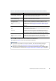
Reset Interface
(Optional, Capture Interface
only)
Select a TCP Reset Interface for traffic picked up through this Capture
Interface. This is the interface through which TCP connection resets
are sent when Reset responses are used in your IPS policy.
What’s Next?
If you want to use VLANs on a Physical Interface, add the VLANs before adding IP
addresses. Proceed to Adding VLAN Interfaces for Master Engines (page 60).
Otherwise, add IP addresses directly to the Physical Interfaces used for Master Engine
communications as instructed in Adding IPv4 Addresses for Master Engines (page 62).
Table 7.2 Physical Interface Properties for Hosted Virtual IPS Engine Communications (Continued)
Options Explanation