
Installation guide

159
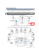
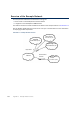
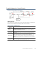
Example Headquarters Intranet Network
Example Headquarters Intranet Network
Illustration C.2 Example Headquarters Intranet Network
HQ IPS Cluster
In the example scenario, HQ IPS Cluster is an inline serial cluster located in the Headquarters
network. The cluster consists of two IPS engine nodes: Node 1 and Node 2.
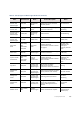
Table C.1 IPS Cluster in the Example Scenario
Network
Interface
Description
Capture
Interfaces
The HQ IPS Cluster’s Capture Interface on each node is connected to a SPAN port
in the Headquarters Intranet switch. All the traffic in this network segment is
forwarded to the SPAN ports for inspection.
Inline Interfaces
The cluster is deployed in the path of traffic between the Firewall and the
Headquarters Intranet switch. All the traffic flows through each node’s Inline
Interface pair.
Normal Interfaces
The Normal Interface on each node is connected to the Headquarters Intranet
switch. Node 1’s IP address is 172.16.1.41 and Node 2’s address is
172.16.1.42. This Normal Interface is used for control connections from the
Management Server, sending events to the HQ Log Server, and for sending TCP
resets.
Heartbeat
Interfaces
The nodes have dedicated Heartbeat Interfaces. Node 1 uses the IP address
10.42.1.41 and Node 2 uses the IP address 10.42.1.42.
SPAN
Management
Network
10.42.1.42
172.16.1.41
10.42.1.41
172.16.1.42
Headquarters
Intranet
HQ Firewall
172.16.1.1
Node 2 Node 1
Switch