PCI-DAS1602/16 Analog and Digital I/O Board User’s Guide Document Revision 7, March, 2009 © Copyright 2009, Measurement Computing Corporation
Your new Measurement Computing product comes with a fantastic extra — Management committed to your satisfaction! Thank you for choosing a Measurement Computing product—and congratulations! You own the finest, and you can now enjoy the protection of the most comprehensive warranties and unmatched phone tech support. It’s the embodiment of our mission: To provide PC-based data acquisition hardware and software that will save time and save money.
Trademark and Copyright Information TracerDAQ, Universal Library, Measurement Computing Corporation, and the Measurement Computing logo are either trademarks or registered trademarks of Measurement Computing Corporation. Windows, Microsoft, and Visual Studio are either trademarks or registered trademarks of Microsoft Corporation LabVIEW is a trademark of National Instruments. CompactFlash is a registered trademark of SanDisk Corporation. XBee and XBee-PRO are trademarks of MaxStream, Inc.
Table of Contents Preface About this User's Guide .......................................................................................................................6 What you will learn from this user's guide ......................................................................................................... 6 Conventions in this user's guide ......................................................................................................................... 6 Where to find more information .
PCI-DAS1602/16 User's Guide Digital input / output ........................................................................................................................................ 24 Interrupts .......................................................................................................................................................... 24 Counter ...............................................................................................................................................
Preface About this User's Guide What you will learn from this user's guide This user's guide explains how to install, configure, and use the PCI-DAS1602/16 board so that you get the most out of its analog, digital, and timing I/O features. This user's guide also refers you to related documents available on our web site, and to technical support resources.
Chapter 1 Introducing the PCI-DAS1602/16 Overview: PCI-DAS1602/16 features The PCI-DAS1602/16 multifunction analog and digital I/O board sets a new standard for high performance data acquisition on the PCI bus. This manual explains how to install and use the PCI-DAS1602/16 board. The PCI-DAS1602/16 is a multifunction measurement and control board designed for the PCI bus. This board can be used for applications such as data acquisition, system timing, and industrial process control.
Chapter 2 Installing the PCI-DAS1602/16 What comes with your PCI-DAS1602/16 shipment? The following items are shipped with the PCI-DAS1602/16. Hardware PCI-DAS1602/16 Additional documentation In addition to this hardware user's guide, you should also receive the Quick Start Guide (available in PDF at www.mccdaq.com/PDFmanuals/DAQ-Software-Quick-Start.pdf).
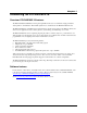
PCI-DAS1602/16 User's Guide Installing the PCI-DAS1602/16 Unpacking the PCI-DAS1602/16 As with any electronic device, you should take care while handling to avoid damage from static electricity. Before removing the PCI-DAS1602/16 from its packaging, ground yourself using a wrist strap or by simply touching the computer chassis or other grounded object to eliminate any stored static charge.
PCI-DAS1602/16 User's Guide Installing the PCI-DAS1602/16 Connecting the board for I/O operations Connectors, cables – main I/O connector The table below lists the board connectors, applicable cables, and compatible accessory products for the PCIDAS1602/16.
PCI-DAS1602/16 User's Guide Installing the PCI-DAS1602/16 Pinout – main I/O connector 8-channel differential mode pin out Signal Name GND EXTERNAL INTERRUPT N/C EXTERNAL D/A PACER GATE D/A INTERNAL PACER OUTPUT A/D INTERNAL PACER OUTPUT N/C N/C -12 V GND +12 V GND N/C N/C N/C N/C N/C N/C N/C N/C N/C N/C N/C N/C N/C N/C FIRSTPORTC Bit 7 FIRSTPORTC Bit 6 FIRSTPORTC Bit 5 FIRSTPORTC Bit 4 FIRSTPORTC Bit 3 FIRSTPORTC Bit 2 FIRSTPORTC Bit 1 FIRSTPORTC Bit 0 FIRSTPORTB Bit 7 FIRSTPORTB Bit 6 FIRSTPORTB Bit 5 FI
PCI-DAS1602/16 User's Guide Installing the PCI-DAS1602/16 16-channel single-ended mode pin out Signal Name GND EXTERNAL INTERRUPT N/C EXTERNAL D/A PACER GATE D/A INTERNAL PACER OUTPUT A/D INTERNAL PACER OUTPUT N/C N/C -12 V GND +12 V GND N/C N/C N/C N/C N/C N/C N/C N/C N/C N/C N/C N/C N/C N/C FIRSTPORTC Bit 7 FIRSTPORTC Bit 6 FIRSTPORTC Bit 5 FIRSTPORTC Bit 4 FIRSTPORTC Bit 3 FIRSTPORTC Bit 2 FIRSTPORTC Bit 1 FIRSTPORTC Bit 0 FIRSTPORTB Bit 7 FIRSTPORTB Bit 6 FIRSTPORTB Bit 5 FIRSTPORTB Bit 4 FIRSTPORTB B
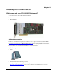
PCI-DAS1602/16 User's Guide Installing the PCI-DAS1602/16 Cable is labeled “Pins 1-50” 49 50 1 2 Key 50 100 The red stripe identifies pin # 1 99 100 Field Wiring connections: SCB-50 CIO-MINI50 CIO-MINI50/DST CIO-TERM100/DST BNC-16DI or BNC-16SE ISO-RACK16/P or ISO-DA02/P with the DADP-5037 adaptor board: CIO-ERB08 or CIO-ERB24 SSR-RACK08 or SSR-RACK24 1 51 Key Connect to the board’s 100-pin I/O connector. Pin 1 is indicated by an arrow on the connector.
PCI-DAS1602/16 User's Guide Installing the PCI-DAS1602/16 Analog signal conditioning and expansion ISO-RACK16/P – 16-channel isolation module mounting rack. ISO-DA02/P – Two-channel, 5B module rack. Details on these products are available at www.mccdaq.com/products/signal_conditioning.aspx. Digital signal conditioning The following digital signal conditioning products have 37-pin connectors. Use the DADP-5037 adaptor board for connections to the C100FF-x cable's 50-pin connectors.
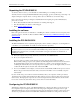
Chapter 3 Functional Details PCI-DAS1602/16 block diagram The PCI-DAS1602/16 provides the following features: 16 single-ended or eight fully differential 16-bit analog inputs Two 16-bit analog outputs 24-bits, high current digital I/O Three 16-bit down counters PCI-DAS1602/16 functions are illustrated in the block diagram shown here. Gain and Offset Autocal Gain and Offset Autocal DAC0 Analog In 16 CH S.E. 8 CH DIFF.
PCI-DAS1602/16 User's Guide Functional Details Software selects the bipolar/unipolar input configuration and input range. The table below lists the analog input ranges and resolutions for the available input configurations and gains. Input range and resolution Bipolar Range Resolution Unipolar Range Resolution ±10 V ±5 V ±2.5 V ±1.25 V 305 µV 153 µV 76.3 µV 38.1 µV 0 to 10 V 0 to 5 V 0 to 2.5 V 0 to 1.25 V 153 µV 76.3 µV 38.1 µV 19.
PCI-DAS1602/16 User's Guide Functional Details Analog outputs The two high-speed 16-bit dual analog outputs are updated via an on-board FIFO and REP OUTSW commands, and provide a 100 kHz maximum update rate. Output ranges are individually configurable with software for ±10 V and ±5 V, 0 to 10 V and 0 to 5 V. The D/A outputs provide rated accuracy to ±5 mA, and are short circuit protected (25 mA limit). The analog outputs are cleared to 0 V on power up or reset.
Chapter 4 Calibrating the PCI-DAS1602/16 The PCI-DAS1602/16 is equipped with software auto calibration. The InstaCal software makes gain and offset corrections to the board using on-board digital potentiometers and trim D/A converters. No user intervention or external equipment is required. The PCI-DAS1602/16 is shipped fully-calibrated from the factory. All adjustments are made via 8-bit calibration DACs or 7-bit digital potentiometers that are referenced to an onboard factory calibrated standard.
PCI-DAS1602/16 User's Guide Calibrating the PCI-DAS1602/16 Analog output calibration The analog output circuits are calibrated for both gain and offset. Offset adjustments for the analog outputs are made in the output buffer section. The tuning range of this adjustment allows for maximum DAC and output buffer offsets. Gain calibration of the analog outputs is performed via DAC reference adjustments. The analog output calibration system is shown in Figure 6.
Chapter 5 Specifications Typical for 25 °C unless otherwise specified. Specifications in italic text are guaranteed by design. All specifications are subject to change without notice. Analog input Table 1.
PCI-DAS1602/16 User's Guide Specifications Accuracy Table 2. Analog input accuracy specifications Range Accuracy BIP10 BIP5 BIP2.5 BIP1.25 UNI10 UNI5 UNI2.5 UNI1.25 ±16 LSB ±6 LSB ±16 LSB ±16 LSB ±8 LSB ±28 LSB ±28 LSB ±28 LSB Accuracy Components Gain error Offset error PGA linearity error Integral linearity error Differential linearity error Trimmable by potentiometer to 0 Trimmable by potentiometer to 0 ±1.3 LSB typ , ±10.0 LSB max ±0.5 LSB typ , ±3.0 LSB max ±0.5 LSB typ, ±2.
PCI-DAS1602/16 User's Guide Specifications Noise performance The following table summarizes the worst case noise performance for the PCI-DAS1602/16. Noise distribution is determined by gathering 50000 samples with inputs tied to ground at the PCI-DAS1602/16 main connector. Data is for both single-ended and differential modes of operation. Table 4. Noise specifications Range ±2 counts ±1 count Max Counts LSBrms* ± 10.00 V ± 5.000 V ± 2.500 V ± 1.250 V 0 - 10.00 V 0 - 5.000 V 0 - 2.500 V 0 - 1.
PCI-DAS1602/16 User's Guide Specifications Analog output Table 6.
PCI-DAS1602/16 User's Guide Specifications Digital input / output Table 9. Digital input/output specifications Digital type Number of I/O Configuration Input high Input low Output high Output low Power-up / reset state Pull-up/pull-down resistors Simultaneous sample and hold trigger 82C55 emulation Input 74LS244 Output 74LS373 24 2 banks of 8 and 2 banks of 4, or 3 banks of 8, or 2 banks of 8 with handshake 2.0 volts min, 7 volts absolute max 0.8 volts max, -0.5 volts absolute min 2.
PCI-DAS1602/16 User's Guide Specifications Counter *Note: Pins 21, 24, and 25 are pulled to logic high via 10K resistors. Table 11. Counter specifications Counter type Configuration 82C54 Two 82C54 chips containing three 16-bit down counters each 82C54A: Counter 0 — ADC residual sample counter. Counter 1 — ADC pacer lower divider Counter 2 — ADC pacer upper divider Source: Gate: Output: Source: Gate: Output: Source: Gate: Output: ADC Clock. Programmable source. End-of-Acquisition interrupt.
PCI-DAS1602/16 User's Guide Specifications Environmental Table 13. Environmental specifications Operating temperature range Storage temperature range Humidity 0 to 70 °C -40 to 100 °C 0 to 95% non-condensing Mechanical Table 14. Mechanical specifications Card dimensions PCI custom type card: 107 mm (H) x 18.5 mm (W) x 292 mm (L) Main connector and pin out Table 15.
PCI-DAS1602/16 User's Guide Specifications Table 16.
PCI-DAS1602/16 User's Guide Specifications Table 17.
Declaration of Conformity Manufacturer: Address: Category: Measurement Computing Corporation 10 Commerce Way Suite 1008 Norton, MA 02766 USA Information technology equipment.
Measurement Computing Corporation 10 Commerce Way Suite 1008 Norton, Massachusetts 02766 (508) 946-5100 Fax: (508) 946-9500 E-mail: info@mccdaq.com www.mccdaq.