
User`s guide


PCIM-DAS1602/16 User's Guide Specifications
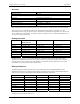
Crosstalk
Crosstalk is defined here as the influence of one channel upon another when scanning two channels at the
specified per channel rate for a total of 50000 samples. A full scale 100Hz triangle wave is input on channel 1.
channel 0 is tied to analog ground at the 100 pin user connector. The table below summarizes the influence of
channel 1 on channel 0 and does not include the effects of noise.
Range 1 kHz Crosstalk
(LSB pk-pk)
10 kHz Crosstalk
(LSB pk-pk)
50 kHz Crosstalk
(LSB pk-pk)
±10.000 V 4 13 24
±5.000 V 2 7 18
±2.500 V 2 5 16
±1.250 V 3 4 14
0 V to +10.000 V 4 8 23
0 V to +5.000 V 2 5 16
0 V to +2.500 V 2 4 16
0 V to +1.250 V 3 3 16
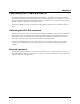
Analog output
D/A converter type MX7548
Resolution 12 bits
Number of channels 2
Channel type Single-ended voltage output
Output range
(jumper selectable per output)
±10 V, ±5 V, 0 to 10 V, or 0 to 5 V using on-board references, or user defined
using external reference
On-board, -10 V and –5 V Reference voltage
(jumper selectable)
External
Independent (D/A0 pin 10 and D/A1 pin 26)
External reference voltage range ±10 V max
External reference input impedance 10 KOhm min
Data transfer Programmed I/O
Throughput
System dependent. Using the Universal Library programmed output function
(cbAOut()) in a loop, in Visual Basic, a typical update rate of 400 Khz can be
expected on a 300 MHz Pentium II based PC.
Monotonicity Guaranteed monotonic over temperature
Slew rate 2.0 V/µs min
Settling time 30 µS max to ±½ LSB for a 20 V step
Current drive ±5 mA min
Output short-circuit duration Indefinite @ 25 mA
Output coupling DC
Output impedance 0.1 ohms max
Output stability Any passive load
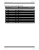
Coding Offset binary
Bipolar mode:
0 code = Vref
4095 code = -Vref – 1LSB, Vref < 0V
-Vref + 1LSB, Vref >0V
Unipolar mode:
0 code = 0V,
4095 code = -Vref – 1LSB, Vref < 0V
-Vref + 1LSB, Vref >0V
Output voltage on power up and reset 0 V ± 10 mV
5-3