
User`s guide


PCIM-DAS1602/16 User's Guide Installing the PCIM-DAS1602/16
Analog and digital connections and configuration
General information on analog and digital signal connections and configuration is contained in the Guide to
Signal Connections (available on our web site at http://www.mccdaq.com/signals/signals.pdf).
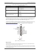
NC 1
NC 3
PB7 5
PB6 7
PB5 9
PB4 11
P B3 13
P B2 15
P B1 17
P B0 19
GND 21
NC 23
GND 25
NC 27
GND 29
NC 31
GND 33
+5V 35
GND 37
NC 39
OR T
OR T
OR T
OR T
OR T
OR T
OR T
OR T
2 +5V
4 GND
6 P C7
OR T
8 P C6
OR T
10 P C5
OR T
12 P C4
OR T
14 P C3
OR T
16 P C2
OR T
18 P C1
OR T
20 P C0
OR T
22 P A7
OR T
24 P A6
OR T
26 P A5
OR T
28 PORT A4
30 PORT A3
32 PORT A2
34 PORT A1
36 PORT A0
38 NC
40 NC
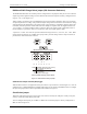
Figure 2-8. Digital I/O connector pin out
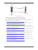
Figure 2-9. BP40-37 connector pin out
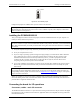
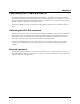
Cabling
20
1
37
19
20
1
37
19
The red stripe
identifies pin # 1
Figure 2-10. C37FF-x cable
20
1
37
19
20
1
37
19
Figure 2-11. C37FFS-x cable
2-8