PCIM-DAS1602/16 Analog & Digital I/O Board User's Guide Document Revision 5, June, 2006 © Copyright 2006, Measurement Computing Corporation
Your new Measurement Computing product comes with a fantastic extra — Management committed to your satisfaction! Refer to www.mccdaq.com/execteam.html for the names, titles, and contact information of each key executive at Measurement Computing. Thank you for choosing a Measurement Computing product—and congratulations! You own the finest, and you can now enjoy the protection of the most comprehensive warranties and unmatched phone tech support.
Trademark and Copyright Information TracerDAQ, Universal Library, InstaCal, Harsh Environment Warranty, Measurement Computing Corporation, and the Measurement Computing logo are either trademarks or registered trademarks of Measurement Computing Corporation. Windows, Microsoft, and Visual Studio are either trademarks or registered trademarks of Microsoft Corporation LabVIEW is a trademark of National Instruments. CompactFlash is a registered trademark of SanDisk Corporation.
Table of Contents About this User's Guide ......................................................................................................................vi What you will learn from this user's guide ........................................................................................................vi Conventions in this user's guide ........................................................................................................................vi Where to find more information ............
PCIM-DAS1602/16 User's Guide Digital I/O connector ..................................................................................................................................................... 5-4 Main connector .............................................................................................................................................................. 5-4 Counter .......................................................................................................................
Preface About this User's Guide What you will learn from this user's guide This user's guide explains how to install, configure, and use the PCIM-DAS1602/16 device so that you get the most out of its analog input and digital I/O features. This user's guide also refers you to related documents available on our web site, and to technical support resources.
Chapter 1 Introducing the PCIM-DAS1602/16 Overview: PCIM-DAS1602/16 features This manual explains how to configure, install, and use your PCIM-DAS1602/16 board. The PCIM-DAS1602/16 is a multifunction measurement and control board designed to operate in computers with PCI bus accessory slots.
PCIM-DAS1602/16 User's Guide Introducing the PCIM-DAS1602/16 Software features For information on the features of InstaCal and the other software included with your PCIM-DAS1602/16, refer to the Quick Start Guide that shipped with your device. The Quick Start Guide is also available in PDF at www.mccdaq.com/PDFmanuals/DAQ-Software-Quick-Start.pdf. Check www.mccdaq.com/download.htm for the latest software version or versions of the software supported under less commonly used operating systems.
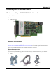
Chapter 2 Installing the PCIM-DAS1602/16 What comes with your PCIM-DAS1602/16 shipment? As you unpack your PCIM-DAS1602/16, make sure that the following components are included. Hardware ! PCIM-DAS1602/16 Additional documentation In addition to this hardware user's guide, you should also receive the Quick Start Guide (available in PDF at www.mccdaq.com/PDFmanuals/DAQ-Software-Quick-Start.pdf).
PCIM-DAS1602/16 User's Guide ! Installing the PCIM-DAS1602/16 Signal termination and conditioning accessories MCC provides signal termination and signal conditioning products for use with the PCIM-DAS1602/16. Refer to the "Field wiring, signal termination and signal conditioning" section for a complete list of compatible accessory products. Unpacking the board As with any electronic device, you should take care while handling to avoid damage from static electricity.
PCIM-DAS1602/16 User's Guide Installing the PCIM-DAS1602/16 Figure 2-1. PCIM-DAS1602/16 switch and jumper locations Before installing the PCIM-DAS1602/16 in the computer, verify that the board is configured with the settings that you want. Review the following information to change the default configuration of a jumper or switch on the PCIM-DAS1602/16 board.
PCIM-DAS1602/16 User's Guide Installing the PCIM-DAS1602/16 A/D Range Select switch The A/D converter range is set by switch S2. This switch controls all A/D channels. Although you cannot run some channels bipolar and some unipolar, you can measure a unipolar input in the bipolar mode (for example, you can monitor a 0 to 5V input with a channel set to the ±5 V range). This switch is factory-configured for bipolar. The A/D Range Select switch shown in Figure 2-3 is configured for unipolar. Figure 2-3.
PCIM-DAS1602/16 User's Guide Installing the PCIM-DAS1602/16 DAC0 and DAC1 Range Select jumper (D/A Converter Reference) The PCIM-DAS1602/16 has an on-board precision voltage reference at jumper P7 that you can use to select the output ranges of the digital to analog converters. Both of the board's D/A outputs are factory-configured with a range of −5 to +5 volts (Figure 2-5.) Analog output is provided by two 12-bit multiplying D/A converters (DAC1 and DAC).
PCIM-DAS1602/16 User's Guide Installing the PCIM-DAS1602/16 10M CLK SEL 1M Figure 2-6. Clock Select jumper Configure this jumper for 10 MHz, unless you have reason to do otherwise. Internal pacer output is also available at pin 20 The internal pacer output driving the A/D converter is also available at pin 20 (CTR 3 Output) on the board's main I/O connector (see Figure 2-7).
PCIM-DAS1602/16 User's Guide Installing the PCIM-DAS1602/16 Table 2-2.
PCIM-DAS1602/16 User's Guide Installing the PCIM-DAS1602/16 Analog and digital connections and configuration General information on analog and digital signal connections and configuration is contained in the Guide to Signal Connections (available on our web site at http://www.mccdaq.com/signals/signals.pdf).
PCIM-DAS1602/16 User's Guide Installing the PCIM-DAS1602/16 19 39 40 1 2 37 Key 20 1 The red stripe identifies pin # 1 Figure 2-12. BP40-37 cable Field wiring, signal termination and signal conditioning You can use the following MCC screw terminal boards to terminate field signals and route them into the PCIMDAS1602/16 board using the C37FF-x or C37FFS-x cable: ! ! CIO-MINI37 – 37-pin screw terminal board. Details on this product are available at www.mccdaq.com/cbicatalog/cbiproduct.
Chapter 3 Programming and Developing Applications After following the installation instructions in Chapter 2, your board should now be installed and ready for use. Although the board is part of the larger DAS family, in general there may be no correspondence among registers for different boards. Software written at the register level for other DAS models will not function correctly with your board.
Chapter 4 Calibrating the PCIM-DAS1602/16 The PCIM-DAS1602/16 is shipped fully calibrated from the factory. For normal environments, you should calibrate your PCIM-DAS1602/16 board using InstaCal's calibration procedures every six months–to-a year. If frequent variations in temperature or humidity are common, recalibrate at least every three months. It requires less than 20 minutes to calibrate the board using InstaCal.
Chapter 5 Specifications Typical for 25 °C unless otherwise specified. Specifications in italic text are guaranteed by design. Power consumption +5V quiescent 820mA typical, 1.
PCIM-DAS1602/16 User's Guide Specifications Accuracy Typical Accuracy Absolute Accuracy ±2.3 LSB ±5.0 LSB Accuracy Components Gain Error Offset Error PGA Linearity Error Integral Linearity Error Differential Linearity Error Trimmable by potentiometer to 0 Trimmable by potentiometer to 0 ±1.3 LSB typ , ±10.0 LSB max ±0.5 LSB typ , ±3.0 LSB max ±0.5 LSB typ, ±2.0 LSB max Each PCIM-DAS1602/16 is tested at the factory to assure the board’s overall error does not exceed ±5 LSB.
PCIM-DAS1602/16 User's Guide Specifications Crosstalk Crosstalk is defined here as the influence of one channel upon another when scanning two channels at the specified per channel rate for a total of 50000 samples. A full scale 100Hz triangle wave is input on channel 1. channel 0 is tied to analog ground at the 100 pin user connector. The table below summarizes the influence of channel 1 on channel 0 and does not include the effects of noise.
PCIM-DAS1602/16 User's Guide Specifications Accuracy Typical accuracy Absolute accuracy ±1 LSB ±2 LSB Accuracy Components Gain error Offset error Integral linearity error Differential linearity error Trimmable by potentiometer to 0 Trimmable by potentiometer to 0 ±0.5 LSB typ, ±1 LSB max ±0.5 LSB typ, ±1 LSB max Total board error is a combination of gain, offset, differential linearity and integral linearity error.
PCIM-DAS1602/16 User's Guide Specifications Counter Counter type Configuration Counter 1 source (software selectable) Counter 1 gate Counter 1 output Counter 2 source (jumper selectable) Counter 2 gate (software enable/disable) Counter 2 output Counter 3 source Counter 3 gate (software enable/disable) Counter 3 output Clock input frequency High pulse width (clock input) Low pulse width (clock input) Gate width high Gate width low Input high Input low Output high Output low Crystal oscillator frequency Fre
PCIM-DAS1602/16 User's Guide Specifications Main connector and pin out Connector type Connector Compatibility 37 pin male "D" connector Identical to CIO-DAS1602/16 Connector 8-channel differential mode pin out Pin 1 2 3 4 5 6 7 8 9 10 11 12 13 14 15 16 17 18 19 Signal Name +5V PC BUS POWER CTR 1 OUT DIG OUT 3 DIG OUT 1 DIG IN 3 DIG IN 1 DIG GND -5V REF OUT D/A 0 OUT D/A0 REF IN CH7 LO CH6 LO CH5 LO CH4 LO CH3 LO CH2 LO CH1 LO CH0 LO AGND Pin 20 21 22 23 24 25 26 27 28 29 30 31 32 33 34 35 36 37 Signa
PCIM-DAS1602/16 User's Guide Specifications Digital input / output connector and pin out Connector type Connector Compatibility Pin 1 3 5 7 9 11 13 15 17 19 21 23 25 27 29 31 33 35 37 39 Signal Name NC NC PORT B 7 PORT B 6 PORT B 5 PORT B 4 PORT B 3 PORT B 2 PORT B 1 PORT B 0 DIG GND NC DIG GND NC DIG GND NC DIG GND +5V PC BUS POWER DIG GND NC 40 pin header Identical to CIO-DAS1602/16 Connector Pin 2 4 6 8 10 12 14 16 18 20 22 24 26 28 30 32 34 36 38 40 Signal Name +5V PC BUS POWER DIG GND PORT C 7 P
Declaration of Conformity Manufacturer: Address: Category: Measurement Computing Corporation 10 Commerce Way Suite 1008 Norton, MA 02766 USA Electrical equipment for measurement, control and laboratory use.
Measurement Computing Corporation 10 Commerce Way Suite 1008 Norton, Massachusetts 02766 (508) 946-5100 Fax: (508) 946-9500 E-mail: info@mccdaq.com www.mccdaq.