
Owner manual


- 7 -
SERVICE
Assembly and disassembly should be performed by a
service technician who has been factory trained on MBW
equipment. The unit should be clean and free of debris.
Pressure washing before disassembly is recommended.
• Prior to assembly, wash all parts in a suitable cleaner or
solvent.
• Check moving parts for wear and failure. Refer to the
Replacement section in this manual for tolerance and
replacement cycles.
• All shafts and housings should be oiled prior to pressing
bearings. Also, ensure that the bearings are pressed
square and are seated properly.
• All gaskets and seals should be replaced after any
disassembly.
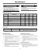
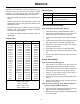
Torque Chart
Service Tools
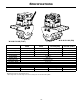
Vibration Head Disassembly
Refer to Vibration Head Assembly, page 16.
1. Follow Disconnecting Wheel Assemblies, page 4
2. Flip vibration head assembly over on a sturdy work
surface to expose the exciter and valve block.
3. Loosen and remove the two main supply lines (#9 &
#12).
4. Loosen and remove the two motor supply lines (#5 &
#6). Note orientation for proper reassembly later.
5. Remove the four exciter nuts (#22), lock washers
(#20), and washers (#21).
6. Note location of any shims for proper reassembly.
7. Attach lifting chain to eyelets on exciter (#11), and lift
out.
8. Remove valve block bolts (#19), and remove valve
block (#13).
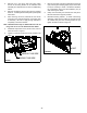
Exciter Disassembly
Refer to Exciter Assembly, page 12.
1. Drain exciter oil by removing both plugs (#19) and
slightly tipping exciter assembly towards the plugs.
2. Remove both socket head cap screws (#21 & #22)
securing hydraulic motor (ref 18). Remove motor.
3. Remove 14 bolts (#23) securing cover (#10) to
exciter housing and remove cover.
4. Remove both snap rings (#4) and slide gears (#11 &
#12) off.
5. Remove 8 bolts (#23) securing cover (#9) to exciter
housing, remove cover.
Note: If removing bearings from shaft assemblies or
housing, bearings MUST be replaced.
6. Press both exciter shafts (#16 & #18) out of housing
(#8), use care not to damage shaft splines.
7. Remove snap rings (#1) and press both bearings (#6)
from housing (#8).
SIZE GRADE 2 GRADE 5 GRADE 8
1/4-20 49 in
•lbs 76 in•lbs 9 ft•lbs
1/4-28 56 in
•lbs 87 in•lbs 10 ft•lbs
5/16-18 8 ft
•lbs 13 ft•lbs 18 ft•lbs
5/16-24 9 ft
•lbs 14 ft•lbs 20 ft•lbs
3/8-16 15 ft
•lbs 23 ft•lbs 33 ft•lbs
3/8-24 17 ft
•lbs 26 ft•lbs 37 ft•lbs
7/16-14 24 ft
•lbs 37 ft•lbs 52 ft•lbs
7/16-20 27 ft
•lbs 41 ft•lbs 58 ft•lbs
1/2-13 37 ft
•lbs 57 ft•lbs 80 ft•lbs
1/2-20 41 ft
•lbs 64 ft•lbs 90 ft•lbs
9/16-12 53 ft
•lbs 82 ft•lbs 115 ft•lbs
5/8-11 73 ft
•lbs 112 ft•lbs 159 ft•lbs
5/8-18 83 ft
•lbs 112 ft•lbs 180 ft•lbs
3/4-16 144 ft
•lbs 200 ft•lbs 315 ft•lbs
1-8 188 ft
•lbs 483 ft•lbs 682 ft•lbs
1-14 210 ft
•lbs 541 ft•lbs 764 ft•lbs
1-1/2-6 652 ft
•lbs 1462 ft•lbs 2371 ft•lbs
M 6 3 ft
•lbs 4 ft•lbs 7 ft•lbs
M 8 6 ft
•lbs 10 ft•lbs 18 ft•lbs
M 10 10 ft
•lbs 20 ft•lbs 30 ft•lbs
CONVERSIONS
in
•lbs x 0.083 = ft•lbs
ft
•lbs x 12 = in•lbs
ft
•lbs x 0.1383 = kg•m
ft
•lbs x 1.3558 = N•m
Part No. Description
16163 Torsion mount install tool
16184
Torsion mount install lubricant
(included with 16163)
00709 Exciter Shim, .005”