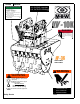
OPERATOR’S SAFETY AND SERVICE MANUAL UV-10K This manual covers the following serial numbers and higher for each model listed: UV-10K 4040020 UVW-24 4042010 UVW-36 4041015 BOOM MOUNTED VIBRATORY ATTACHMENTS MBW, Inc. MBW (UK) Ltd. 250 Hartford Rd • PO Box 440 Slinger, WI 53086-0440 Phone: (262) 644-5234 Fax: (262) 644-5169 Email: mbw@mbw.com Website: www.mbw.com Units 2 & 3 Cochrane Street Bolton BL3 6BN, England Phone: 44 (0) 1204 387784 Fax: 44 (0) 01204 387797 Email: mbwuk@btinternet.
TABLE OF CONTENTS Safety Information . . . . . . . . . . . . . . . . . . . . . . 1 Replacing Shockmounts. . . . . . . . . . . . . . . . . . . . . . . 5 Introduction . . . . . . . . . . . . . . . . . . . . . . . . . . . . . . . . . 1 Service. . . . . . . . . . . . . . . . . . . . . . . . . . . . . . . . 7 Safety Precautions . . . . . . . . . . . . . . . . . . . . . . . . . . . 1 Safety Decals . . . . . . . . . . . . . . . . . . . . . . . . . . . . . . . 1 Specifications. . . . . . . . . . . . . . . . .
WARNING CALIFORNIA PROPOSITION 65 WARNING Engine exhaust and some of its constituents are known in the state of California to cause cancer, birth defects, and other reproductive harm.
SAFETY INFORMATION Introduction SAFE DRESS: Do not wear loose clothing, rings, wristwatches, etc. near machinery. This Safety Alert Symbol is used to call attention to items or operations which may be dangerous to those operating or working with this equipment. The symbol can be found throughout this manual and on the unit. Please read these warnings and cautions, along with all decals, carefully before attempting to operate the unit.
RETURN PRESSURE OPERATING INSTRUCTIONS 1. Back pressure in return lines MUST NOT EXCEED 200 PSI. 2. Hydraulic Requirements: Pressure 1500-3000 psi Volume 20-70 gpm 3. Check for loose hardware after every 20 hours of operation. 4. Do not run exciter when attachment is not in contact of backfill. 5. Not recommended for use on excavators over 60,000 lbs. 18854 U.S. PATENT 5,244,306 U.S.
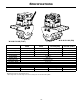
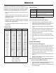
SPECIFICATIONS W-36 & UV-10K (PIN) W-24 & UV-10K (FLAT) W-24 W-36 UV-10K (PIN) UV-10K (FLAT) Excavator Connection Flat Top Style Flat Top Style Adjustable Pin Style Flat Top Style Static Weight* 1367 lbs (620 Kg)* 1750 lbs (794 Kg)* 1019 lbs (462 Kg)* 1095 lbs (497 Kg)* Overall Width 24” (61 cm) 36” (91 cm) 24” (61 cm) 24” (61 cm) Drum width 21” (53 cm) 33” (84 cm) - - 1500-3000 psi 1500-3000 psi 20-70 gpm 20-70 gpm 1” Male JIC 37º 1” Male JIC 37º Drum diameter 28” (71 cm)
OPERATION Introduction Adjusting Pin-Type Mount MBW equipment is intended for use in very severe applications. The UV-10K can be ordered with an adjustable mounting system which can adjust to allow for excavator booms 9” to 15” wide. The center distance is fixed at 17.5”. Refer to Pin Mount Assembly, page 14. This parts manual contains only standard parts. Variations of these parts as well as other special parts are not included.
MAINTENANCE WARNING CAUTION Always exercise the stopping procedure before servicing or lubricating the unit. Always verify fluid levels and check for leaks after changing fluids. After servicing the unit, replace and fasten all guards, shields, and covers to their original positions before resuming operation. Do not drain oil onto ground, into open streams, or down sewage drains.
2. Remove the 6 nuts (#13) and bolts (#12) which secure the mounting bracket to the vibration head assembly and seperate the two with a suitable lifting device. 3. Remove old primary shock mounts (#1) by pressing them out. A small hydraulic bottle jack or porta power works best. 4. After removing old mount, lubricate the new shock mount and inner cylindrical surface of UV frame prior to assembly. Be sure to apply enough lubricant to completely cover both surfaces. 7.
SERVICE Service Tools Assembly and disassembly should be performed by a service technician who has been factory trained on MBW equipment. The unit should be clean and free of debris. Pressure washing before disassembly is recommended. Part No. • Prior to assembly, wash all parts in a suitable cleaner or solvent. • Check moving parts for wear and failure. Refer to the Replacement section in this manual for tolerance and replacement cycles.
8. (A puller will be required to do this step) Remove snap rings (#7) from both exciter shafts (#16 & #18) and remove inner races. 9. Remove both snap ring (#1) securing bearings (#5) in cover (#9). Remove 4 bolts and washers (#17 & #20). 9. Install plugs (#19) and fill with 17oz of exciter oil, install fill plug (#24). Figure 3 SHIELDS 10. Support cover (#9) and use a brass punch to tap out bearings (#5) alternate from side to side of each bearing to eliminate binding of the bearing.
Wheel Assembly WARNING Refer to Wheel Assembly, page 18. See Specifications, page 3 for weight of your machine. If unit is lifted improperly, it may fall and cause serious injury or death. 1. Remove the seal from one side of the bearing (#5). 2. Insert bearing, seal-less side first, into the hub (#4). 4. Loosen and remove the 12 bolts (#13) that secure the wheel hubs to the frame. 3. Assemble the bearing and hub subassembly onto the axle. 5. Carefully lift the machine off the wheel.
This page intentionally left blank.
REPLACEMENT PARTS The warranty is stated in this book on page 18. Failure to return the Warranty Registration Card renders the warranty null and void. MBW has established a network of reputable distributors/ dealers with trained mechanics and full facilities for maintenance and rebuilding, and to carry an adequate parts stock in all areas of the country. Their sales engineers are available for professional consultation.
2))6(7 21 02725 72:$5'6 723 2) $66(0%/< Exciter Assembly - 12 -
ITEM 1. 2. 3. 4. 5. 6. 7. 8. 9. 10. 11. 12. 13. 14. 15. 16. 17. 18. 19. 20. 21. 22. 23. 24. 25. PART NO. 01000 19930 06457 07203 07456 07458 07469 09451 09453 09455 09457 09485 09741 09745 14267 18808 18841 19046 F0227SPP F061604HCS F061608SCS F061610SCS F061612FWS F0618SPP F06LW 01291 DESCRIPTION RETAINING RING, INTERNAL 5000-315 RETAINING RING, EXTERNAL 1.
Bracket Assemblies - 14 -
ITEM 1. 2. 3. 4. 5. 6. 7. 8. 9. 10. 11. 12. 13. 14. PART NO.
Vibration Head Assembly - 16 -
ITEM 1. 2. 3. 4. 5. 6. 7. 8. 9. 10. 11. 12. 13. 14. 15. 16. 17. 18. 19. 20. 21. 22. 23. 24. 25. PART NO.
Wheel Assembly - 18 -
ITEM 1. 2. 3. 4. 5. 6. 7. 8. 9. 10. 11. 12. 13. 14. 15. PART NO. 01177 18826 18837 18792 18861 19286 19290 19291 19292 19293 20234 20235 F081308SCS F081316HCS F08LW F101116HCS F101118HCS F1011HN F10LW 24W 36W DESCRIPTION FITTING, GREASE STD SCRAPER TOOTH, WELDED, 1.5 SCRAPER TOOTH, WELDED, 2.
WARRANTY WHAT DOES THIS WARRANTY COVER? MBW, Incorporated (MBW) warrants each New Machine against defects in material and workmanship for a period of twelve (12) months. "New Machine" means a machine shipped directly from MBW or authorized MBW dealer to the end user. This warranty commences on the first day the machine is sold, assigned to a rental fleet, or otherwise put to first use. MBW warrants each Demonstration Machine against defects in material and workmanship for a period of six (6) months.
NOTES - 21 -
NOTES - 22 -