
Manual


- 6 -
SERVICE
Assembly and disassembly should be performed by a
service technician who has been factory trained on MBW
equipment. The unit should be clean and free of debris.
Pressure washing before disassembly is recommended.
• Prior to assembly, wash all parts in a suitable cleaner or
solvent.
• Check moving parts for wear and failure. Refer to the
Replacement section in this manual for tolerance and
replacement cycles.
• All shafts and housings should be oiled prior to pressing
bearings. Also, ensure that the bearings are pressed
square and are seated properly.
• All bearings should be replaced when rebuilding any
exciter or gearbox.
• All gaskets and seals should be replaced after any
disassembly.
Torque Chart
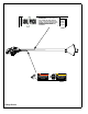
Service Tools
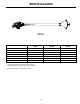
Handle Disassembly
Refer to Handle Assembly, page 12.
1. Remove three screws (#18) securing handle and
remove, taking care to not lose spring (#10).
2. Remove two screws (#15) holding bottom cover (#5)
and remove cover.
3. Using a wrench across flats on valve spool (#4),
loosen and remove screw securing trigger (#8).
4. Use a pick or small screwdriver, remove shaft wiper
(#2).
5. Remove snap ring (#15).
6. Using a wrench across the flats on valve spool (# 4),
remove screw securing lower spool (#7).
7. Pull spool (#4) our the top of the body. Guide (#6) will
come out with spool.
8. Push lower valve spool (#7) out the bottom of the
valve body (#9).
9. Insert a long standard bladed screwdriver through the
inlet of the valve body to unscrew the gage (#11).
Handle Assembly
Refer to Handle Assembly, page 12.
Note: All o-rings and seals should be replaced after any
disassembly.
1. Thread gage (#11) into body (#9) using a long
standard blade screwdriver and thread sealing
compound.
2. Place o-rings (#12, 14) into grooves on valve spool
(#4). Coat o-rings with grease and insert spool (#4)
into body (#9).
3. Place o-ring (#14) into groove on lower valve spool
(#7), coat o-ring with grease, and insert into bottom of
body. Secure to valve spool (#14) with screw (#17).
Use wrench across flats on valve spool to tighten
screw.
4. Place o-ring in groove on upper guide (#6), coat with
grease, and insert into main body over the valve
spool.
SIZE GRADE 2 GRADE 5 GRADE 8
1/4-20 49 in
•lbs 76 in•lbs 9 ft•lbs
1/4-28 56 in
•lbs 87 in•lbs 10 ft•lbs
5/16-18 8 ft
•lbs 13 ft•lbs 18 ft•lbs
5/16-24 9 ft
•lbs 14 ft•lbs 20 ft•lbs
3/8-16 15 ft
•lbs 23 ft•lbs 33 ft•lbs
3/8-24 17 ft
•lbs 26 ft•lbs 37 ft•lbs
7/16-14 24 ft
•lbs 37 ft•lbs 52 ft•lbs
7/16-20 27 ft
•lbs 41 ft•lbs 58 ft•lbs
1/2-13 37 ft
•lbs 57 ft•lbs 80 ft•lbs
1/2-20 41 ft
•lbs 64 ft•lbs 90 ft•lbs
9/16-12 53 ft
•lbs 82 ft•lbs 115 ft•lbs
5/8-11 73 ft
•lbs 112 ft•lbs 159 ft•lbs
5/8-18 83 ft
•lbs 112 ft•lbs 180 ft•lbs
3/4-16 144 ft
•lbs 200 ft•lbs 315 ft•lbs
1-8 188 ft
•lbs 483 ft•lbs 682 ft•lbs
1-14 210 ft
•lbs 541 ft•lbs 764 ft•lbs
1-1/2-6 652 ft
•lbs 1462 ft•lbs 2371 ft•lbs
M 6 3 ft
•lbs 4 ft•lbs 7 ft•lbs
M 8 6 ft
•lbs 10 ft•lbs 18 ft•lbs
M 10 10 ft
•lbs 20 ft•lbs 30 ft•lbs
CONVERSIONS
in
•lbs x 0.083 = ft•lbs
ft
•lbs x 12 = in•lbs
ft
•lbs x 0.1383 = kg•m
ft
•lbs x 1.3558 = N•m
Part No. Description
20563 VALVE GREASE, SILICONE,.21 oz
20565 REBUILD KIT, SOIL PICK