OPERATOR’S SAFETY AND SERVICE MANUAL SP80 SP125 SP160 This manual covers the following serial numbers and higher for each model listed: SP80 . . . . . . . . . . . . . . . . . . . . . 3830125 SP125 . . . . . . . . . . . . . . . . . . . . 3830125 SP160 . . . . . . . . . . . . . . . . . . . . 3830125 SOIL PICK MBW, Inc. 250 Hartford Rd • PO Box 440 Slinger, WI 53086-0440 Phone: (262) 644-5234 Fax: (262) 644-5169 Email: mbw@mbw.com Website: www.mbw.com MBW (UK) Ltd. MBW France S.A.R.
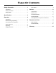
TABLE OF CONTENTS Safety Information . . . . . . . . . . . . . . . . . . . . . . 1 Tips & Tricks. . . . . . . . . . . . . . . . . . . . . . . . . . . . . . . . 4 Introduction . . . . . . . . . . . . . . . . . . . . . . . . . . . . . . . . . 1 Service. . . . . . . . . . . . . . . . . . . . . . . . . . . . . . . . 6 Safety Precautions . . . . . . . . . . . . . . . . . . . . . . . . . . . 1 Safety Decals . . . . . . . . . . . . . . . . . . . . . . . . . . . . . . . 1 Specifications. . . . . . . . . . . .
This page intentionally left blank.
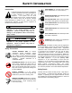
SAFETY INFORMATION Introduction SAFE DRESS: Do not wear loose clothing, rings, wristwatches, etc. near machinery. This Safety Alert Symbol is used to call attention to items or operations which may be dangerous to those operating or working with this equipment. The symbol can be found throughout this manual and on the unit. Please read these warnings and cautions, along with all decals, carefully before attempting to operate the unit.
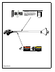
US PATENT #5,170,943 MINIMIZE SCATTER BY KEEPING BOTTOM OF DEFLECTOR SHIELD THREE INCHES (3) ABOVE NOZZLE. PULL TRIGGER AND CHECK PRESSURE GAUGE. IF INDICATED PRESSURE IS NOT BETWEEN 100 AND 125 PSI (INDICATED BY A GREEN SECTION ON SOME GAUGES), INCREASE AIR SUPPLY BEFORE PROCEEDING.
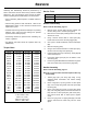
SPECIFICATIONS 63 SP80 SP125 SP160 Volume of Air 80 cfm (38 L/s) 125 cfm (59 L/s) 160 cfm (76 L/s) Minimum Operating Pressure 100 psi (689 kPa) 100 psi (689 kPa) 100 psi (689 kPa) Maximum Operating Pressure 125 psi (862 kPa) 125 psi (862 kPa) 125 psi (862 kPa) Exit Velocity 1476 mph (660 M/s) 1476 mph (660 M/s) 1476 mph (660 M/s) 4 in (10 cm) 4 in (10 cm) 8 in (20 cm) 6.7 lbs (3.0 kg) 6.7 lbs (3.0 kg) 6.7 lbs (3.
OPERATION Introduction WARNING This parts manual contains only standard parts. Variations of these parts as well as other special parts are not included. Contact your local MBW distributor for assistance in identifying parts not included in this manual. Do not operate the Soil Pick at a pressure greater than 125 psi. 4. Before Starting & Operating Operating • REMEMBER! It is the owner’s responsibility to communicate information on the safe use and proper operation of this unit to the operators.
2. 3. 4. The Soil Pick is not an elaborate blow pipe. Conventional blow pipes produce subsonic air stream velocities between 500 and 600 mph, and cannot provide the cutting edge required for soil excavation. Blow pipes can be used for moving loose debris, but even then are outperformed by the Soil Pick. 7. The Soil Pick does not require lubrication. The air supply must be free of oil to achieve proper performance. 8. The Soil Pick is a selective excavator.
SERVICE Assembly and disassembly should be performed by a service technician who has been factory trained on MBW equipment. The unit should be clean and free of debris. Pressure washing before disassembly is recommended. Service Tools 20563 VALVE GREASE, SILICONE,.21 oz • Prior to assembly, wash all parts in a suitable cleaner or solvent. 20565 REBUILD KIT, SOIL PICK Part No. Description Handle Disassembly • Check moving parts for wear and failure.
5. Insert retaining ring (#15) and make certain it is fully seated in groove. 8. Attach Handle (#3) to body with three screws (#17). Use Medium strength loctite on these screws. 6. Coat the inner diameter of the dust wiper (#2) with grease and insert into main body. The lip of the seal should be facing out, and the shoulder should be flush with the surface of the body. 9. Assemble lower cover (#5) to body with two screws (#15) 7. 10.
This page intentionally left blank.
REPLACEMENT PARTS The warranty is stated in this book on page 14. Failure to return the Warranty Registration Card renders the warranty null and void. '(&$/ /2&$7,21 MBW has established a network of reputable distributors/ dealers with trained mechanics and full facilities for maintenance and rebuilding, and to carry an adequate parts stock in all areas of the country. Their sales engineers are available for professional consultation.
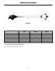
ACCESSORIES Main Assembly - 10 -
ITEM 1. 2. 3. 4. 5. 6. 7. 8. 9. 10. 11. 12. 13. 14. 15. 16. PART NO.
Handle Assembly - 12 -
ITEM 1. 2. 3. 4. 5. 6. 7. 8. 9. 10. 11. 12. 13. 14. 15. 16. 17. 18. PART NO. 17250 19430 20451 20452 20453 20454 20455 20456 20457 20459 20460 20461 20462 20463 20587 F023202BCS F033205BCS F042006BCS 20565 DESCRIPTION FITTING, PLUG SHAFT WIPER SEAL, 3/4 ID X 1-1/8 OD HANDLE, SOIL PICK VALVE SPOOL COVER, BOTTOM GUIDE, TOP BOTTOM SPOOL (20455: before SN 3830125 use 20677) TRIGGER VALVE BODY, MACHINED SPRING, TRIGGER GAGE, SLOTTED O-RING, 9/16 ID X .125 O-RING, 1 ID X .0625 O-RING, 5/8 ID X .
WARRANTY WHAT DOES THIS WARRANTY COVER? MBW, Incorporated (MBW) warrants each New Machine against defects in material and workmanship for a period of twelve (12) months. "New Machine" means a machine shipped directly from MBW or authorized MBW dealer to the end user. This warranty commences on the first day the machine is sold, assigned to a rental fleet, or otherwise put to first use. MBW warrants each Demonstration Machine against defects in material and workmanship for a period of six (6) months.