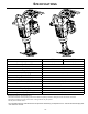
OPERATOR’S SAFETY AND SERVICE MANUAL R442 This manual covers the following serial numbers and higher for each model listed: R442H...........................4420 00 SMART RAMMERS MBW, Inc. MBW (UK) Ltd. 250 Hartford Rd • PO Box 440 Slinger, WI 53086-0440 Phone: (262) 644-5234 Fax: (262) 644-5169 Email: mbw@mbw.com Website: www.mbw.
TABLE OF CONTENTS Safety Information . . . . . . . . . . . . . . . . . . . . . . 1 General. . . . . . . . . . . . . . . . . . . . . . . . . . . . . . . . . . . . 7 Introduction . . . . . . . . . . . . . . . . . . . . . . . . . . . . . . . . . 1 Handle Removal. . . . . . . . . . . . . . . . . . . . . . . . . . . . . 7 Safety Precautions . . . . . . . . . . . . . . . . . . . . . . . . . . . 1 Safety Decals . . . . . . . . . . . . . . . . . . . . . . . . . . . . . . . 1 Engine Removal . . . . . . . . . .
WARNING CALIFORNIA PROPOSITION 65 WARNING Engine exhaust and some of its constituents are known in the state of California to cause cancer, birth defects, and other reproductive harm.
SAFETY INFORMATION Introduction SAFE DRESS: Do not wear loose clothing, rings, wristwatches, etc. near machinery. This Safety Alert Symbol is used to call attention to items or operations which may be dangerous to those operating or working with this equipment. The symbol can be found throughout this manual and on the unit. Please read these warnings and cautions, along with all decals, carefully before attempting to operate the unit.
CAUTION WARNING OPERATION OF THIS EQUIPMENT MAY CREATE SPARKS THAT CAN START FIRES AROUND DRY VEGETATION. A SPARK ARRESTER MAY BE REQUIRED. THE OPERATOR SHOULD CONTACT LOCAL FIRE AGENCIES FOR LAWS OR REGULATIONS 19791 RELATING TO FIRE PREVENTION 19791 Read the Operating Instructions before operating this piece of equipment. Keep unauthorized and untrained people away from this equipment. ROTATING & MOVING PARTS! Make sure all guards and safety devices are in place.
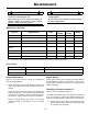
SPECIFICATIONS + +$ Operating Weight - lbs(kg) 442H 442HA 150 (68) 154 (70) Height - in(cm) 41 (104) Width - in(cm) 15 (38) Length - in(cm) 29 (74) Engine Honda GX100 Shoe (W x L) in (cm) 11 x 13 (28 x 33) 1 dBa 93 dBA Operating Noise Level Compaction Force lbf (kN) 3800 (16.9) Travel Speed ft/min(m/min) 55 (16.8) Compaction Area sqft/hr (sqm/hr) 2900 (269) Percussion Rate blows/min up to 720 Engine Speed rpm 3500 Fuel Capacity - gal(L) 1.1 (4.
OPERATION Introduction 4. MBW equipment is intended for use in very severe applications. They are powered by four cycle engines and are available in different sizes and a selection of engines. Choke engine if necessary (you may not need to choke a warm engine). 5. Pull starter rope repeatedly until engine starts. 6. Move choke lever to open position. 7. Allow engine to warm up for one or two minutes. This parts manual contains only standard parts.
MAINTENANCE WARNING CAUTION Always exercise the stopping procedure before servicing or lubricating the unit. Always verify fluid levels and check for leaks after changing fluids. After servicing the unit, replace and fasten all guards, shields, and covers to their original positions before resuming operation. Do not drain oil onto ground, into open streams, or down sewage drains.
2. If the oil is not visible in the sight gauge, add oil as required. See Fluid Levels for recommended type of oil. Changing Percussion System Oil Refer to Lower Unit Assembly, page 16. 1. Remove the drain plug (#4) below the sight glass (#9) on the back of the spring box guard (#8). 2. Place an oil drain pan behind the shoe and tip the rammer back so the handle is on the ground. Refer to Gearbox and Lower Unit Assembly, page 18. -6- 3.
SERVICE Assembly and disassembly should be performed by a service technician who has been factory trained on MBW equipment. The unit should be clean and free of debris. Pressure washing before disassembly is recommended. Service Tools 01629 Rubber Test Mat • Prior to assembly, wash all parts in a suitable cleaner or solvent. 07205 Bellows Installation Tool 07552 Blind Hole Bearing Puller Tool 20194 Service Kit 20260 Spring box Tool Part No. • Check moving parts for wear and failure.
Clutch Removal 8. Refer to Engine Assembly, page 22. 1. Remove the jam (#13) nut and slide the clutch off engine crank shaft. 2. Reinstall the clutch, making sure key remains in place and aligned with keyway 3. Reinstall jam nut with medium strength thread locker and tighten to 60 ft lbs (N•m). Remove the gearbox assembly from the lower unit assembly. See Figure 2. Gearbox Removal NOTE: It is necessary to remove the Handle and the Engine to remove the Gearbox.
Breather Removal 1. Remove the hex head cap screw (#28) from the top of the breather assembly (#14). 2. Remove the plain washer (#29), cap (#17) and filter (#15). 3. Use a pipe wrench to remove the breather tube (#16). letters facing up. Apply a light coat of oil (see Fluid Levels, page 5 for proper oil type) to the needle bearing after installation. CAUTION Do not disassemble the breather assembly. 7. Place a retaining ring (#10) over the large shaft of the crank gear (#20).
Lower Unit Disassembly NOTE: The lower unit can be separated from the drive unit (engine, gearbox and handle) without completely disassembling the rammer. If the lower unit has not already been separated, follow the “Gearbox Removal” instructions. Refer to Lower Unit Assembly, page 16. Shoe and Spring box Guard Removal 6. While holding the hex nuts from turning, slowly and evenly back off the rods on the cover side of the spring box. 7.
8. Insert the spring box tool (MBW #20260) rods into the spring box as shown in Figure 4. Figure 4 9. Slowly draw the cover down onto the spring box by alternately tightening each rod. 3. Align the connecting rod (page 14, #5) with the ram head and install the piston connecting pin (#5) with the threaded hole in the pin facing out. 4. Install retaining ring (#6) into ram head. Be sure retaining ring is completely seated into groove in ram head. 5.
Parts Replacement Cycles and Tolerances Bearings Replace anytime a bearing is rough, binding, discolored or removed from housing or shaft. Bellows Replace when they are worn, cracked, or to the point of leaking. Clutch Replace clutch if shoes and/or springs show signs of heat damage or if it does not disengage below 2000 rpm. Crank Gear Replace if teeth are cracked or if they become sharp. Engine Components Refer to your engine manufacturer’s Owner’s Manual. Guide Bushings Replace if a 0.025” (0.
REPLACEMENT PARTS The warranty is stated in this book on page 24. Failure to return the Warranty Registration Card renders the warranty null and void. MBW has established a network of reputable distributors/ dealers with trained mechanics and full facilities for maintenance and rebuilding, and to carry an adequate parts stock in all areas of the country. Their sales engineers are available for professional consultation.
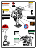
Gearbox Assembly - 14 -
ITEM 1. 2. 3. 4. 5. 6. 7. 8. 9. 10. 11. 12. 13. 14. 15. 16. 17. 18. 19. 20. 21. 22. 23. 24. 25. 26. 27. 28. 29. PART NO. 01001 01103 01105 01244 06161 06259 06262 06264 06265 06266 06274 06413 06423 06904 06905 06908 06910 09476 09618 13733 15959 16021 16451 20047 20160 F01PW F061605FWS F081304HCS F08SW DESCRIPTION RETAINING RING, EXT. 5100-137 BEARING, BALL BEARING, BALL RETAINING RING, EXT. 5160-112 ROD ASSEMBLY, CONNECTING (includes item #7) BEARING, NEEDLE BUSHING RETAINING RING, INT.
Lower Unit Assembly - 16 -
ITEM 1. 2. 3. 4. 5. 6. 7. 8. 9. 10. 11. 12. 13. 14. 15. 16. 17. 18. 19. 20. 21. 22. 23. 24. 25. 26. PART NO. 06173 06237 06327 07154 09618 11694 16311 16330 18276 18693 18694 18695 19585 20027 20039 20041 20043 20044 20162 20336 F042005FSS F042006FWS F042007FWS F071418SCS F07LW F0813ELN F081318HCS F08LW 20177 20173 DESCRIPTION COVER, SPRINGBOX O-RING, 4.33 ID X 0.103 DIA BUSHING RING, CLAMPING, LOWER FITTING, PLUG PARKER 4HP50N BELLOWS, 4 PLY RING, CLAMPING, UPPER O-RING, 2.72 ID X 0.
Gearbox and Lower Unit Assembly - 18 -
ITEM 1. 2. 3. 4. 5. 6. 7. 8. PART NO.
6833/,(' :,7+ (1*,1( ,167$// 7$&+ :,5( 7+58 &/$03 $66(0%/( &/$03 72 (1*,1( 7$&+ 02'(/6 21/< $,5 ,17$.( 72 32,17 '2:1 )25:$5' 6(( (1*,1( 3$*( )25 (/%2: $'$37(5 .
ITEM 1. 2. 3. 4. 5. 6. 7. 8. 9. 10. 11. 12. 13. 14. 15. 16. 17. 18. 19. 20. 21. 22. 23. 24. 25. 26. 27. 28. 29. 30. PART NO. 20387 01052 01145 07351 07916 20476 15183 20422 16414 16586 18510 18511 18515 18742 19899 14946 20713 20719 F032402FSS F042004FWS F051807FWS F051808FWS F0518FN 20549 DESCRIPTION FUEL FILTER, IN-LINE CLAMP, HOSE CLAMP, SPRING TORSION MOUNT FERRULE, THROTTLE LEVER CAP, 1-3/4” HOSE, FUEL 1-1/2” LONG HOSE, FUEL, 3/16 I.D.
$'$37(5 (/%2: .
ITEM 1. 2. 3. 4. 5. 6. 7. 8. 9. 10. 11. 12. 13. 14. PART NO. 17164 17197 17217 18053 18055 18527 18530 F0518FN M12CHJN M08C025FWS 20539 15. 16. 17. 18. 19. DESCRIPTION STUD, Mounted in gearbox (page 18, #4) Install with red-high strength loctite. ADAPTER, GX100 REDUCER, BARBED, (Supplied with engine) CLIP, FUEL LINE, (Supplied with engine) FUEL LINE, 3/16 ID, (Supplied with engine) HEX HEAD FLANGE SCREW, M8-1.25 X 40mm, (Supplied with engine) PIN, DOWEL, 6mm X 10mm (420H) (Not provided by MBW Inc.
WARRANTY WHAT DOES THIS WARRANTY COVER? MBW, Incorporated (MBW) warrants each New Machine against defects in material and workmanship for a period of twelve (12) months. "New Machine" means a machine shipped directly from MBW or authorized MBW dealer to the end user. This warranty commences on the first day the machine is sold, assigned to a rental fleet, or otherwise put to first use. MBW warrants each Demonstration Machine against defects in material and workmanship for a period of six (6) months.
NOTES: 25
NOTES: 26