
Manual


- 7 -
SERVICE
Assembly and disassembly should be performed by a
service technician who has been factory trained on MBW
equipment. The unit should be clean and free of debris.
Pressure washing before disassembly is recommended.
• Prior to assembly, wash all parts in a suitable cleaner or
solvent.
• Check moving parts for wear and failure. Refer to the
Replacement section in this manual for tolerance and
replacement cycles.
• All shafts and housings should be oiled prior to pressing
bearings. Also, ensure that the bearings are pressed
square and are seated properly.
• All bearings should be replaced when rebuilding any
exciter or gearbox.
• All gaskets and seals should be replaced after any
disassembly.
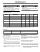
Torque Chart
Service Tools
General
The disassembly and assembly procedures given on the
next few pages are intended for a complete dismantling of
the rammer. Read the following sections carefully. It is not
necessary to follow the complete disassembly procedure
when only partial disassembly is required. If repairs have to
be made to the Lower Assembly only, it is recommended
that the drive unit (engine, gearbox and handle) be removed
from the lower unit. See “Lower Unit Disassembly”.
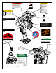
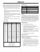
Handle Removal
Refer to (HL) Handle Assembly, page 20.
1. Turn the fuel valve (#10) to the “off” position.
2. Loosen the hose clamp (#2) at the engine end of the
fuel line (#8). Disconnect the fuel line.
3. Remove the flat head screws (#19) holding the
throttle (#15) to the handle (#16).
4. Remove the four flange head cap screws (#22) and
flange nuts (#23) securing the handle to the torsion
mounts (#4).
5. Lift the handle (#16) from the rammer.
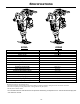
Engine Removal
NOTE: It is not necessary to remove the handle to take
the engine off the machine.
Refer to Engine Assembly, page 21.
1. Follow steps 1 through 3 under “Handle Removal“.
2. For models with large air cleaner (HA), remove clamp
from air tube and disconnect air tube from engine.
3. While supporting the engine, remove the four hex
flange nuts (#12) holding the engine (#11) and engine
adapter plate (#2) assembly to the studs (#1) in
gearbox.
4. Remove the engine assembly from the rammer.
SIZE GRADE 2 GRADE 5 GRADE 8
1/4-20 49 in
•lbs 76 in•lbs 9 ft•lbs
1/4-28 56 in
•lbs 87 in•lbs 10 ft•lbs
5/16-18 8 ft
•lbs 13 ft•lbs 18 ft•lbs
5/16-24 9 ft
•lbs 14 ft•lbs 20 ft•lbs
3/8-16 15 ft
•lbs 23 ft•lbs 33 ft•lbs
3/8-24 17 ft
•lbs 26 ft•lbs 37 ft•lbs
7/16-14 24 ft
•lbs 37 ft•lbs 52 ft•lbs
7/16-20 27 ft
•lbs 41 ft•lbs 58 ft•lbs
1/2-13 37 ft
•lbs 57 ft•lbs 80 ft•lbs
1/2-20 41 ft
•lbs 64 ft•lbs 90 ft•lbs
9/16-12 53 ft
•lbs 82 ft•lbs 115 ft•lbs
5/8-11 73 ft
•lbs 112 ft•lbs 159 ft•lbs
5/8-18 83 ft
•lbs 112 ft•lbs 180 ft•lbs
3/4-16 144 ft
•lbs 200 ft•lbs 315 ft•lbs
1-8 188 ft
•lbs 483 ft•lbs 682 ft•lbs
1-14 210 ft
•lbs 541 ft•lbs 764 ft•lbs
1-1/2-6 652 ft
•lbs 1462 ft•lbs 2371 ft•lbs
M 6 3 ft
•lbs 4 ft•lbs 7 ft•lbs
M 8 6 ft
•lbs 10 ft•lbs 18 ft•lbs
M 10 10 ft
•lbs 20 ft•lbs 30 ft•lbs
CONVERSIONS
in
•lbs x 0.083 = ft•lbs
ft
•lbs x 12 = in•lbs
ft
•lbs x 0.1383 = kg•m
ft
•lbs x 1.3558 = N•m
Part No. Description
01629 Rubber Test Mat
07205 Bellows Installation Tool
07552 Blind Hole Bearing Puller Tool
20194 Service Kit
20260 Spring box Tool