
User Manual


- 10 -
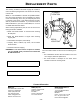
SERVICE
Assembly and disassembly should be performed by a
service technician who has been factory trained on MBW
equipment. The unit should be clean and free of debris.
Pressure washing before disassembly is recommended.
• Prior to assembly, wash all parts in a suitable cleaner or
solvent.
• Check moving parts for wear and failure. Refer to the
Replacement section in this manual for tolerance and
replacement cycles.
• All shafts and housings should be oiled prior to pressing
bearings. Also, ensure that the bearings are pressed
square and are seated properly.
• All gaskets and seals should be replaced after any
disassembly.
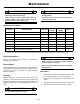
Torque Chart
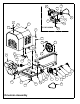
Engine Shroud Removal
Refer to Drivetrain Assembly, page 16.
1. Disconnect wiring harness (#18) from engine by un-
screwing ring terminal from engine and unplugging
bullet connector.
2. Remove automatic safety grid lifter from safety grid.
3. Remove four bolts (#25), washers (#27), and lock-
nuts (#26) securing shroud to frame.
4. Carefully lift shroud straight up to avoiding damaging
engine or drive components. Approximate weight is
85 pounds.
Engine Shroud Installation
Refer to Drivetrain Assembly, page 16.
1. Lift shroud over engine and drive components and
lower it straight down onto frame. Hold grid opener
out of the way while lowering.
2. Align shroud with edges of frame and tighten bolts
(#25), washers (#27), and locknuts (#26) in place.
3. Lift grid opener into position and pin to safety grid.
4. Connect wiring harness (#18) to engine by grounding
the ring terminal to the engine and inserting the bullet
connector into the splice terminal.
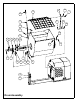
Drum Removal
Refer to Drum Assembly, page 14.
1. Remove engine shroud before attemping to remove
mixing drum.
2. Mark the front and rear pillow block (#5) locations on
the frame to aid in the alignment during installation.
3. Remove all four bolts (#25), washers (#28 & #10),
lockwashers (#27), and locknuts (#26) holding drum
pillow blocks to frame.
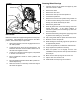
4. If lifting drum by hoist, wrap chain around main shaft
and pass chain through paddles to stabilize. If lifting
drum by forklift, place blocks on forks to prevent drum
from rolling. Approximate weight is 250 to 300
pounds, depending on model.
Drum Installation
Refer to Drum Assembly, page 14.
1. Lower drum onto frame supports. Pillow blocks (#5)
should be snug to trunnions (#8) to eliminate
excessive endplay.
SIZE GRADE 2 GRADE 5 GRADE 8
1/4-20 49 in
•lbs 76 in•lbs 9 ft•lbs
1/4-28 56 in
•lbs 87 in•lbs 10 ft•lbs
5/16-18 8 ft
•lbs 13 ft•lbs 18 ft•lbs
5/16-24 9 ft
•lbs 14 ft•lbs 20 ft•lbs
3/8-16 15 ft
•lbs 23 ft•lbs 33 ft•lbs
3/8-24 17 ft
•lbs 26 ft•lbs 37 ft•lbs
7/16-14 24 ft
•lbs 37 ft•lbs 52 ft•lbs
7/16-20 27 ft
•lbs 41 ft•lbs 58 ft•lbs
1/2-13 37 ft
•lbs 57 ft•lbs 80 ft•lbs
1/2-20 41 ft
•lbs 64 ft•lbs 90 ft•lbs
9/16-12 53 ft
•lbs 82 ft•lbs 115 ft•lbs
5/8-11 73 ft
•lbs 112 ft•lbs 159 ft•lbs
5/8-18 83 ft
•lbs 112 ft•lbs 180 ft•lbs
3/4-16 144 ft
•lbs 200 ft•lbs 315 ft•lbs
1-8 188 ft
•lbs 483 ft•lbs 682 ft•lbs
1-14 210 ft
•lbs 541 ft•lbs 764 ft•lbs
1-1/2-6 652 ft
•lbs 1462 ft•lbs 2371 ft•lbs
M 6 3 ft
•lbs 4 ft•lbs 7 ft•lbs
M 8 6 ft
•lbs 10 ft•lbs 18 ft•lbs
M 10 10 ft
•lbs 20 ft•lbs 30 ft•lbs
CONVERSIONS
in
•lbs x 0.083 = ft•lbs
ft
•lbs x 12 = in•lbs
ft
•lbs x 0.1383 = kg•m
ft
•lbs x 1.3558 = N•m