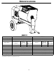
OPERATOR’S SAFETY AND SERVICE MANUAL MM91 & MM121 This manual covers the following serial numbers and higher for each model listed: MM121 . . . . . . . . . . . . . . . . . . . 7090001 MM91 . . . . . . . . . . . . . . . . . . . . 7150001 MORTAR & PLASTER MIXERS MBW, Inc. MBW (UK) Ltd. MBW FRANCE S.A.R.L. 250 Hartford Rd • PO Box 440 Slinger, WI 53086-0440 Phone: (262) 644-5234 Fax: (262) 644-5169 Email: mbw@mbw.com Website: www.mbw.
TABLE OF CONTENTS Safety Information . . . . . . . . . . . . . . . . . . . . . . 1 Changing Hydraulic Filter . . . . . . . . . . . . . . . . . . . . . . 7 Introduction . . . . . . . . . . . . . . . . . . . . . . . . . . . . . . . . . 1 Changing Hydraulic Oil & Suction Strainer. . . . . . . . . 7 Safety Precautions . . . . . . . . . . . . . . . . . . . . . . . . . . . 1 Greasing Wheel Bearings . . . . . . . . . . . . . . . . . . . . . 7 Safety Decals . . . . . . . . . . . . . . . . . . . . . . . . . .
WARNING CALIFORNIA PROPOSITION 65 WARNING Engine exhaust and some of its constituents are known in the state of California to cause cancer, birth defects, and other reproductive harm.
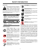
SAFETY INFORMATION Introduction SAFE DRESS: Do not wear loose clothing, rings, wristwatches, etc. near machinery. This Safety Alert Symbol is used to call attention to items or operations which may be dangerous to those operating or working with this equipment. The symbol can be found throughout this manual and on the unit. Please read these warnings and cautions, along with all decals, carefully before attempting to operate the unit.
CAUTION(PRECAUCIÓN) Improper towing can lead to damage or injury. CAUTION(PRECAUCIÓN) Read the operating instructions before operating this piece of equipment. Lea las Instrucciones Operativas antes de hacer funcionar esta parte del equipo. Before Towing: 1. Check running gear and tow bar. 2. Lock drum in tow position. 3. Check tow pin for proper instal-lation and good condition. 4. USE SAFETY CHAINS when towing.
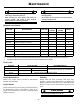
SPECIFICATIONS MM91 MM121 Batch Capacity 9 cu. ft. (0.26 cu. m.) 12 cu. ft. (0.34 cu. m.) Batch Size 3 - 3.5 bags 3.5 - 4.5 bags Engine / Motor Engine / Motor Speed Drivetrain (389 cm)³ Baldor 5 hp (1-phase) 230 V - 23 A 3300 rpm 1725 rpm Honda Gx390 23.7 in³ Baldor 5 hp Honda Gx390 23.7 in³ (3-phase) (389 cm)³ 230 V - 13.4 A 460 V - 6.7 A 1750 rpm Hydraulic Pump to Hydraulic Motor 3300 rpm Baldor 5 hp (1-phase) 230 V - 23 A Baldor 5 hp (3-phase) 230 V - 13.4 A 460 V - 6.
OPERATION Introduction 7. Move choke lever to open position. MBW equipment is intended for use in very severe applications. They are powered by reliable four cycle engines. 8. Allow engine to warm up for one or two minutes. Starting Motor 1. This parts manual contains only standard parts. Variations of these parts as well as other special parts are not included. Contact your local MBW distributor for assistance in identifying parts not included in this manual.
Towing WARNING Always stop engine before adding fuel. Stop engine before leaving mixer unattended for any amount of time. 1. Stop the engine or motor. 2. Close and latch the engine shroud. 3. Secure the tow pole and safety chains to the vehicle. WARNING Stopping Motor 1. Push motor lever to “STOP”, or center, position. Always check that axle, front leg, and tow pole hardware is tight before towing. 2. Let motor cool for one or two minutes if warm. Make sure safety bolt is in place. 3.
MAINTENANCE WARNING CAUTION Always exercise the stopping procedure before servicing or lubricating the unit. Always verify fluid levels and check for leaks after changing fluids. After servicing the unit, replace and fasten all guards, shields, and covers to their original positions before resuming operation. Do not drain oil onto ground, into open streams, or down sewage drains.
WARNING Always stop engine or motor and disconnect spark plug wire or power cord before placing hands or objects inside drum. Always reconnect safety grid opener to grid after cleaning drum. Lubrication 1. Grease both trunnions and pillow blocks daily. There are two grease fittings on each end of the drum. 3. Remove hydraulic filter which is accessible from the front opening of the engine shroud, or from underneath the frame. 4. Apply clean oil to filter gasket, and install new filter (MBW #08164).
SERVICE Engine Shroud Removal Assembly and disassembly should be performed by a service technician who has been factory trained on MBW equipment. The unit should be clean and free of debris. Pressure washing before disassembly is recommended. Refer to Shroud & Chassis Assembly, page 12. 1. Disconnect wiring harness (#11) from engine by unscrewing ring terminal from engine and unplugging bullet connector from splice terminal (#5). 2. Disconnect automatic grid opener from grid. 3.
Drum Installation 14. Install new seal kits into the back side of each trunnion in the following order: Steel Washer, Soft Black Seal, Steel Washer, Soft Black Seal, Steel Washer, Hard Red Seal. Refer to Drum Assembly, page 14. 1. 2. Lower drum onto frame supports. Pillow blocks (#5) should be snug to trunnions (#8) to eliminate excessive endplay. 15. Slide trunnions onto each shaft end and bolt in place. 16. Slide bearing locking collar onto front shaft end and align shaft flush with collar.
8. Reinstall inspection cover. 9. Reinstall the engine shroud. 1,850 psi, the relief valve needs adjustment. NOTE: If pressure climbs over 1,850 psi, the engine may stall. Hydraulic Relief Valve Adjustment 1. Remove the engine shroud. 2. Install a pressure gage using the side port on the left side of the valve block (pressure port, P). The pressure gage must read to 2,000 psi. 3. Start engine and check that all hydraulic controls are operating properly. 4.
REPLACEMENT PARTS The warranty is stated in this book on page 22. Failure to return the Warranty Registration Card renders the warranty null and void. MBW has established a network of reputable distributors/ dealers with trained mechanics and full facilities for maintenance and rebuilding, and to carry an adequate parts stock in all areas of the country. Their sales engineers are available for professional consultation.
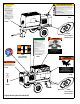
00 Shroud & Chassis Assembly - 12 -
ITEM 1. 2. 3. 4. 5. 6. 7. 8. 9. 10. 11. 12. 13. 14. 15. 16. 17. 18. 19. 20. 21. 22. 23. 24. 25. 26. 27. 28. 29. 30. 31. 32. 33. 34. 35. 36. 37. 38. 39 PART NO.
11 18 3 1 25 8 4 9 12 10 26 16 22 2 15 21 7 6 16 23 24 2 25 5 13 19 20 14 17 Drum Assembly - 14 -
ITEM 1. 2. 3. 4. 5. 6. 7. 8. 9. 10. 11. 12. 13. 14. 15. 16. 17. 18. 19. 20. 21. 22. 23. 24. 25. 26. PART NO.
02725 Paddle Assembly - 16 -
ITEM 1. 2. 3. 4. 5. 6. 7. 8. 9. 10. 11. 12. 13. 14. 15. 16. 17. PART NO.
Hydraulic Components - 18 -
ITEM 1. 2. 3. 4. 5. 6. 7. 8. 9. 10. 11. 12. 13. 14. 15. 16. 17. 18. 19. 20. 21. 22. 23. 24. 25. 26. 27. 28. 29. 30. 31. 32. 33. 34. 35. 36. 37. PART NO.
Engine Assembly - 20 -
ITEM 1. 2. 3. 4. 5. 6. 7. 8. 9. 10. 11. 12. 13. 14. 15. 16. 17. 18. 19. 20. 21. 22 PART NO.
WARRANTY WHAT DOES THIS WARRANTY COVER? MBW, Incorporated (MBW) warrants each New Machine against defects in material and workmanship for a period of twelve (12) months. "New Machine" means a machine shipped directly from MBW or authorized MBW dealer to the end user. This warranty commences on the first day the machine is sold, assigned to a rental fleet, or otherwise put to first use. MBW warrants each Demonstration Machine against defects in material and workmanship for a period of six (6) months.