OPERATOR’S SAFETY AND SERVICE MANUAL MM120 This manual covers the following serial numbers and higher for each model listed: MM120 . . . . . . . . . . . . . . . . . . . 7070040 MORTAR & PLASTER MIXERS MBW, Inc. MBW (UK) Ltd. MBW FRANCE S.A.R.L. 250 Hartford Rd • PO Box 440 Slinger, WI 53086-0440 Phone: (262) 644-5234 Fax: (262) 644-5169 Email: mbw@mbw.com Website: www.mbw.com Units 2 & 3 Cochrane Street Bolton BL3 6BN, England Phone: 01204 387784 Fax: 01204 387797 Z.A.
TABLE OF CONTENTS Safety Information . . . . . . . . . . . . . . . . . . . . . . 1 Greasing Wheel Bearings . . . . . . . . . . . . . . . . . . . . 10 Introduction . . . . . . . . . . . . . . . . . . . . . . . . . . . . . . . . . 1 Service. . . . . . . . . . . . . . . . . . . . . . . . . . . . . . . 11 Safety Precautions . . . . . . . . . . . . . . . . . . . . . . . . . . . 1 Safety Decals . . . . . . . . . . . . . . . . . . . . . . . . . . . . . . . 1 Specifications. . . . . . . . . . . . . . . . . . .
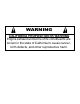
WARNING CALIFORNIA PROPOSITION 65 WARNING Engine exhaust and some of its constituents are known in the state of California to cause cancer, birth defects, and other reproductive harm.
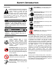
SAFETY INFORMATION Introduction SAFE DRESS: Do not wear loose clothing, rings, wristwatches, etc. near machinery. This Safety Alert Symbol is used to call attention to items or operations which may be dangerous to those operating or working with this equipment. The symbol can be found throughout this manual and on the unit. Please read these warnings and cautions, along with all decals, carefully before attempting to operate the unit.
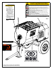
CAUTION(PRECAUCIÓN) CAUTION(PRECAUCIÓN) Improper towing can lead to damage or injury. Read the operating instructions before operating this piece of equipment. Lea las Instrucciones Operativas antes de hacer funcionar esta parte del equipo. Keep unauthorized, inexperienced, untrained people away from this equipment. Mantenga a las personas no autorizadas y sin entrenamiento alejadas de este equipo. Before Towing: 1. Check running gear and tow bar. 2. Lock drum in tow position. 3.
WARNING WARNING ADVERTENCIA ADVERTENCIA MOVING PARTS CAN CRUSH AND CUT KEEP HANDS CLEAR! SHUT OFF ENGINE OR MOTOR BEFORE SERVICING. ENGINE EXHAUST IS HAZARDOUS IF INHALED USE ONLY IN A WELL VENTILATED AREA LAS PIEZAS MÓVILES PUEDEN IMPACTAR Y CORTAR ¡MANTENGA ALEJADAS SUS MANOS! APAGUE EL MOTOR ANTES DEL SERVICIO.
MIXER(MEZCLADORA) OPERATING INSTRUCTIONS INSTRUCCIONES DE OPERACIÓN PUSH TO STOP PULSE PARA DETENER WARNING OPERATION OF THIS EQUIPMENT MAY CREATE SPARKS THAT CAN START FIRES AROUND DRY VEGETATION. A SPARK ARRESTER MAY BE REQUIRED. THE OPERATOR SHOULD CONTACT LOCAL FIRE AGENCIES FOR LAWS OR REGULATIONS 19791 RELATING TO FIRE PREVENTION 19791 16546 15071 1. 2. 3. 4. 5. 6. 7. 8. 9. Check oil in engine crankcase. MAKE SURE grid is CLOSED before starting and during operation.
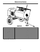
SPECIFICATIONS MM120 MM120 Batch Capacity 12 cu. ft. (0.34 cu. m.) Batch Size 3.5 - 4.5 bags Gas Engine Honda GX390 20.6 in.³ (389 cm³) Engine Speed 3300 rpm Drivetrain Enclosed Gearbox and Mechanical Clutch Axle 61” torsion axle Wheels ST175/80D13 high-speed Size - W x L x H 61 x 86 x 57 in (155 x 218 x 145 cm) Weight 985 lbs (447 kg) Charging Height 49 in (124 cm) Specifications subject to change without notice.
OPERATION Introduction 8. MBW equipment is intended for use in very severe applications. They are powered by four cycle engines and are available in different sizes and a selection of engines. Allow engine to warm up for one or two minutes. Operating This parts manual contains only standard parts. Variations of these parts as well as other special parts are not included. Contact your local MBW distributor for assistance in identifying parts not included in this manual. 1. Open throttle fully. 2.
3. Close and latch the engine shroud. 4. Rotate the drum into the locked position, and check that it is locked in place. 5. Secure the tow pole and safety chains to the vehicle. WARNING Always check that axle, front leg, and tow bar hardware is tight before towing. Make sure safety bolt is in place. Check the condition of the pin on the tow bar and make sure it is secure. Remove any loose debris from the mixer before towing on roads. Check that safety chains cross each other when attached.
MAINTENANCE WARNING CAUTION Always exercise the stopping procedure before servicing or lubricating the unit. Always verify fluid levels and check for leaks after changing fluids. After servicing the unit, replace and fasten all guards, shields, and covers to their original positions before resuming operation. Do not drain oil onto ground, into open streams, or down sewage drains.
Lubrication 1. Grease both trunnions and pillow blocks daily. There are two grease fittings on each side of the drum. 2. Oil clutch yoke shaft every 50 hours at the pivot points (see Figures 1 & 2). FIGURE 2 Checking Gearbox Oil OIL PIVOT 1. Remove check plug on side of gearbox. 2. Oil level should be even with bottom of check plug. 3. If low, add oil by removing the breather plug on top of gearbox. Change oil if it appears dark brown or smells burnt. Gearbox is shipped with 32 oz.
Greasing Wheel Bearings 9. 1. Jack the rear end of the mixer and support by side rails so that mixer is stable. 2. Remove the wheel. 3. Remove the dust cover. 4. Remove the cotter pin from the spindle nut. 5. Unscrew the spindle nut. 6. Remove the hub from the spindle, being careful not to allow the outer bearing cone to fall out. The inner bearing cone will be retained by the seal. 7. Remove the grease seal. 8. Wash all grease and oil from the bearing cones and inspect each roller.
SERVICE Assembly and disassembly should be performed by a service technician who has been factory trained on MBW equipment. The unit should be clean and free of debris. Pressure washing before disassembly is recommended. Engine Shroud Removal Refer to Gearbox Drivetrain Assembly, page 20. 1. Disconnect wiring harness (#7) from engine by unscrewing ring terminal from engine and unplugging bullet connector. 2. Remove automatic safety grid lifter from safety grid. 3.
2. Check alignment between the two coupler sprockets. Sprockets must be parallel and in-line. Adjust drum location if necessary. 3. Bolt pillow blocks to frame using four bolts (#25), washers (#28 & #10), lockwashers (#27), and locknuts (#26). 4. Dump drum to check for binding. If binding is noticed, loosen bolts and realign pillow blocks. 5. Reassemble the coupling chain and install the connecting link. 6. Reinstall the engine shroud. 20.
Engine & Gearbox Disassembly Refer to Gearbox Drive Assembly, page 18. 2. Support gearbox so it stands upright. Remove magnetic drain plug (#6) and drain oil. 3. Remove engine and gearbox from mixer. See Engine & Gearbox Removal, page 12. Tip gearbox down onto a support so clutch housing faces down. 4. 2. Remove the access cover (#13) which is secured by four bolts (#15). Remove sprocket from output shaft. Use a puller if necessary. 5. 3.
4. Press both bearings (#1) onto shaft. 5. Install key (#24) into pinion shaft (#9). 6. Press gear (#13) onto shaft and install retaining ring (#19). 7. Press both bearings (#5) onto shaft. 8. Install key (#18) into output shaft (#15). 9. Press gear (#12) onto shaft and install retaining ring (#21). 13. Place all three assembled gear shafts into housing and push them together until the bearings line up with the bores and they drop into place. 14.
REPLACEMENT PARTS The warranty is stated in this book on page 18. Failure to return the Warranty Registration Card renders the warranty null and void. STAMPED LOCATION MBW, Inc. has established a network of reputable distributors with trained mechanics and full facilities for maintenance and rebuilding, and to carry an adequate parts stock in all areas of the country. Their sales engineers are available for professional consultation.
Drum Assembly - 16 -
ITEM 1. 2. 3. 4. 5. 6. 7. 8. 9. 10. 11. 12. 13. 14. 15. 16. 17. 18. 19. 20. 21. 22. 23. 24. 25. 26. 27. 28. 29. PART NO.
Gearbox Drive Assembly - 18 - 5 21 12 11 6 20 4 22 20 16 13 2 18 14 19 17 7 15 9 3 10 8 1
ITEM 1. 2. 3. 4. 5. 6. 7. 8. 9. 10. 11. 12. 13. 14. 15. 16. 17. 18. 19. 20. 21. 22. PART NO.
3 13 17 16 4 7 22 1 24 21 6 15 14 5 18 10 11 9 2 25 8 29 23 31 29 30 28 19 26 28 27 12 20 Gearbox Drivetrain Assembly - 20 -
ITEM 1. 2. 3. 4. 5. 6. 7. 8. 9. 10. 11. 12. 13. 14. 15. 16. 17. 18. 19. 20. 21. 22. 23. 24. 25. 26. 27. 28. 29. 30. 31. PART NO.
Gearbox Assembly - 22 - 23 28 16 8 17 1 2 21 10 12 14 15 20 19 18 13 3 24 11 9 26 5 22 29 4 25 27 6 7
ITEM 1. 2. 3. 4. 5. 6. 7. 8. 9. 10. 11. 12. 13. 14. 15. 16. 17. 18. 19. 20. 21. 22. 23. 24. 25. 26. 27. 28. 29. PART NO.
6 18 12 18 10 2 16 17 23 20 14 21 3 24 19 22 20 15 13 11 1 8 7 9 Frame & Axle Assembly - 24 - 4 5
ITEM 1. 2. 3. 4. 5. 6. 7. 8. 9. 10. 11. 12. 13. 14. 15. 16. 17. 18. 19. 20. 21. 22. 23. 24. 25 26 PART NO. 01158 01170 01175 06442 05844 16728 16564 16773 16743 16771 17195 17158 17194 17305 17523 F0212CP F061640CB F0616FN F081310HCS F08SW F0813ELN F1614SCN F121628HCS F12LW F1216HN 18077 18076 DESCRIPTION PIN, HITCH SEAL, GREASE COVER, DUST WHEEL, ST175/80D13 WHEEL NUT, 1/2-20 FRAME, MM120 TOW POLE, BALL HITCH (Includes 19-22) TOW POLE, PINTLE HITCH (Includes 19-22) LEG, FRONT CHAIN, SAFETY (10 ft.
(1*,1( (1' Paddle Assembly - 26 -
ITEM 1. 2. 3. 4. 5. 6. 7. 8. 9. 10. 11. 12. 13. 14. 15. 16. 17. PART NO.
WARRANTY WHAT DOES THIS WARRANTY COVER? MBW, Incorporated (MBW) warrants each New Machine against defects in material and workmanship for a period of twelve (12) months. "New Machine" means a machine shipped directly from MBW or authorized MBW dealer to the end user. This warranty commences on the first day the machine is sold, assigned to a rental fleet, or otherwise put to first use. MBW warrants each Demonstration Machine against defects in material and workmanship for a period of six (6) months.
NOTES - 29 -
NOTES - 30 -