OPERATOR’S SAFETY AND SERVICE MANUAL MK8 75 This manual covers the following serial numbers and higher for each model listed: MK8-75 . . . . . . . . . . . . . . . . . . 1780001 RIDE ON TROWELS MBW, Inc. MBW (UK) Ltd. 250 Hartford Rd • PO Box 440 Slinger, WI 53086-0440 Phone: (262) 644-5234 Fax: (262) 644-5169 Email: mbw@mbw.com Website: www.mbw.com Units 2 & 3 Cochrane Street Bolton BL3 6BN, England Phone: 01204 387784 Fax: 01204 387797 L18872 / 05.06.B ©MBW, Inc.
TABLE OF CONTENTS Safety Information . . . . . . . . . . . . . . . . . . . . . . 1 Introduction . . . . . . . . . . . . . . . . . . . . . . . . . . . . . . . . . 1 Safety Precautions . . . . . . . . . . . . . . . . . . . . . . . . . . . 1 Safety Decals . . . . . . . . . . . . . . . . . . . . . . . . . . . . . . . 1 Reduction Gear Oil. . . . . . . . . . . . . . . . . . . . . . . . . . . 6 Lifting . . . . . . . . . . . . . . . . . . . . . . . . . . . . . . . . . . . . . 7 Storage. . . . . . . . . . . . . . .
WARNING CALIFORNIA PROPOSITION 65 WARNING Engine exhaust and some of its constituents are known in the state of California to cause cancer, birth defects, and other reproductive harm.
SAFETY INFORMATION Introduction SAFE DRESS: Do not wear loose clothing, rings, wristwatches, etc. near machinery. This Safety Alert Symbol is used to call attention to items or operations which may be dangerous to those operating or working with this equipment. The symbol can be found throughout this manual and on the unit. Please read these warnings and cautions, along with all decals, carefully before attempting to operate the unit.
CAUTION Read the Operating Instructions before operating this piece of equipment. Keep unauthorized and untrained people away from this equipment. ROTATING & MOVING PARTS! Make sure all guards and safety devices are in place. Wear approved hearing protection, foot protection, eye protection and head protection. STOP SHUT OFF the motor before servicing or cleaning. DO NOT RUN in an enclosed area. The engine produces carbon monoxide, a POISONOUS GAS.
SPECIFICATIONS MK8 75 Dimensions 61 x 30.7 x 41in. (1550x780x970mm) Weight 374.8lbs. (170kg) Motor Honda 13HP Max Engine RPM 3600 RPM Min / Max Blade RPM 70 / 130 RPM Rotor Diameter 29.5in. (750mm) Max Forward Speed 295 ft./min. (90 m/min.) Acoustic Level At Drivers Seat 97.1 (dB) Trowel Path 76in. (1930.
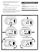
OPERATION Introduction Starting Engine MBW equipment is intended for use in very severe applications. They are powered by four cycle engines and are available in different sizes and a selection of engines. 1. Close the choke. Choking may not be necessary on warm engines. 2. Leave throttle, turn engine switch to run. This parts manual contains only standard parts. Variations of these parts as well as other special parts are not included.
subsequent smoothing operations continue increasing the blade inclination until obtaining the desired finish. WARNING Always stop the engine before: Stopping Engine 1. Move throttle to idle and release the two safety stop levers. 2. Close the fuel valve and turn switch to stop. Adding fuel. Leaving the equipment unattended for any amount of time. Before making any repairs or adjustments to the machine.
MAINTENANCE WARNING CAUTION Always follow the stopping procedure before servicing or lubricating the unit. Always verify fluid levels and check for leaks after changing fluids. After servicing the unit, replace and fasten all guards, shields, and covers to their original positions before resuming operation. Do not drain oil onto ground, into open streams, or down sewage drains.
3. Remove filler plug, located above sight gage, and fill until the sight gage is half full. Refer to Fluid levels on page 6 for type and quantity. 4. Replace filler plug. Always check the state of wear of the blades and if they are damaged or bent, replace them. They must all be replaced at the same time. Lifting 1. Clean the machine. 2. Slightly lift the machine off the ground (about 4”). 3. Remove the blades by removing the bolts though arm.
SERVICE Torque Chart Assembly and disassembly should be performed by a service technician who has been factory trained on MBW equipment. The unit should be clean and free of debris. Pressure washing before disassembly is recommended. SIZE 1/4-20 1/4-28 5/16-18 5/16-24 3/8-16 3/8-24 7/16-14 7/16-20 1/2-13 1/2-20 9/16-12 5/8-11 5/8-18 3/4-16 1-8 1-14 1-1/2-6 M6 M8 M 10 • Prior to assembly, wash all parts in a suitable cleaner or solvent. • Check moving parts for wear and failure.
REPLACEMENT PARTS The warranty is stated in this book on page 18. Failure to return the Warranty Registration Card renders the warranty null and void. MBW has established a network of reputable distributors/ dealers with trained mechanics and full facilities for maintenance and rebuilding, and to carry an adequate parts stock in all areas of the country. Their sales engineers are available for professional consultation.
Main Assembly - 10 -
Control Assembly - 11 -
Drive Assembly - 12 -
Right Blade and Gearbox Assembly - 13 -
Left Blade and Gearbox Assembly - 14 -
Engine Assembly - 15 -
0878 LIFTING HANDLE 18064 LIFTING SLING Accessories - 16 -
NOTES - 17 -
WARRANTY 1. 2. 3. MBW warrants each new machine against defects in material and workmanship under normal use and service for a period of six (6) months. This warranty commences the first day the machine is sold, assigned to a rental fleet, or otherwise put to first use. The obligation under this warranty is limited to the replacement or repair of parts and/or machine at MBW factory branches or at authorized MBW distributors. Machines altered or modified without MBW written consent voids this warranty.