
User Manual


- 9 -
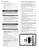
SERVICE
Assembly and disassembly should be performed by a
service technician who has been factory trained on MBW
equipment. The unit should be clean and free of debris.
Pressure washing before disassembly is recommended.
• Prior to assembly, wash all parts in a suitable cleaner or
solvent.
• Check moving parts for wear and failure. Refer to the
Replacement section in this manual for tolerance and
replacement cycles.
• All shafts and housings should be oiled prior to pressing
bearings. Also, ensure that the bearings are pressed
square and are seated properly.
• All bearings should be replaced when rebuilding any
exciter or gearbox.
• All gaskets and seals should be replaced after any
disassembly.
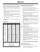
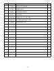
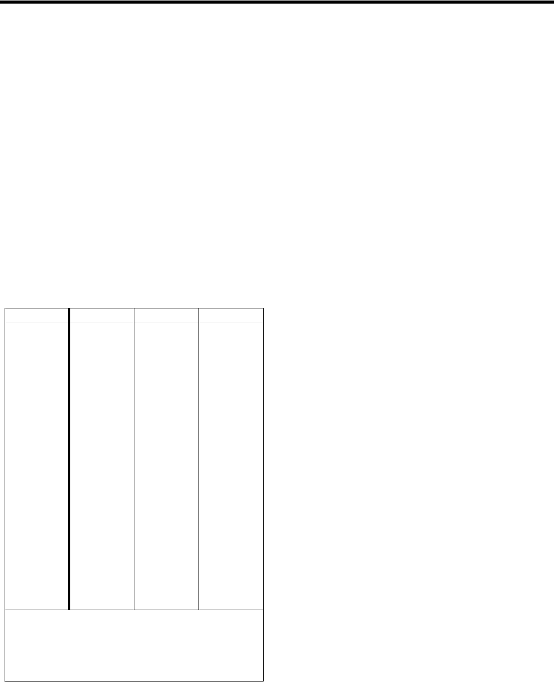
Torque Chart
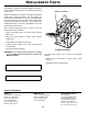
Replacing Shifter Cable Assembly
Refer to Figure 1 Shifter Cable, page 7.
1. Unbolt and remove the ball joint (item #5).
2. Remove the jam nut (item #7), dust seal (item #3),
hex nuts (item #1) and washers (item #2).
3. Slide the shifter cable out of the angle bracket (item
#4).
4. Unbolt the shifter assembly (item #8) from the handle
and remove from the compactor.
5. Install the new shifter assembly.
6. Remove all necessary parts from the cable end and
slide it through the engine deck and angle bracket
(item #4).
7. Install the washer (item #2), hex nuts (item #1), dust
seal (item #3), jam nut (item #7) and ball joint (item
#5) onto the cable.
8. Bolt the ball joint (item #5) to the actuator arm (item
#6).
9. Before tightening the two hex nuts (item #1) to the
angle bracket, adjust the cable (See Checking the
Shifter Cable, page 7).
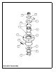
Gas Engine Removal
Refer to Honda Main Assembly, page 22.
1. Let the machine cool and clean all visible debris from
the machine before disassembly.
2. Remove the (4) 3/8” flanged capscrews securing the
rollcage to the engine deck and remove the rollcage.
3. If equipped with throttle cable, remove the air cleaner
cover and air filter.
4. Remove throttle cable from engine. Be careful not to
loose throttle cable clamp.
5. Remove the (4) 1/4” hex head capscrews securing
the beltguard to the side plate on the engine deck and
remove the beltguard and belt.
6. Now is a good time to inspect and consider replacing
the v-belt.
7. Remove the (4) hex head capscrews securing the
engine to the engine deck and remove the engine.
Diesel Engine Removal
Refer to Diesel Main Assembly, page 24.
1. Let the machine cool and clean all visible debris from
the machine before disassembly.
SIZE GRADE 2 GRADE 5 GRADE 8
1/4-20 49 in
•lbs 76 in•lbs 9 ft•lbs
1/4-28 56 in
•lbs 87 in•lbs 10 ft•lbs
5/16-18 8 ft
•lbs 13 ft•lbs 18 ft•lbs
5/16-24 9 ft
•lbs 14 ft•lbs 20 ft•lbs
3/8-16 15 ft
•lbs 23 ft•lbs 33 ft•lbs
3/8-24 17 ft
•lbs 26 ft•lbs 37 ft•lbs
7/16-14 24 ft
•lbs 37 ft•lbs 52 ft•lbs
7/16-20 27 ft
•lbs 41 ft•lbs 58 ft•lbs
1/2-13 37 ft
•lbs 57 ft•lbs 80 ft•lbs
1/2-20 41 ft
•lbs 64 ft•lbs 90 ft•lbs
9/16-12 53 ft
•lbs 82 ft•lbs 115 ft•lbs
5/8-11 73 ft
•lbs 112 ft•lbs 159 ft•lbs
5/8-18 83 ft
•lbs 112 ft•lbs 180 ft•lbs
3/4-16 144 ft
•lbs 200 ft•lbs 315 ft•lbs
1-8 188 ft
•lbs 483 ft•lbs 682 ft•lbs
1-14 210 ft
•lbs 541 ft•lbs 764 ft•lbs
1-1/2-6 652 ft
•lbs 1462 ft•lbs 2371 ft•lbs
M 6 3 ft
•lbs 4 ft•lbs 7 ft•lbs
M 8 6 ft
•lbs 10 ft•lbs 18 ft•lbs
M 10 10 ft
•lbs 20 ft•lbs 30 ft•lbs
CONVERSIONS
in
•lbs x 0.083 = ft•lbs
ft
•lbs x 12 = in•lbs
ft
•lbs x 0.1383 = kg•m
ft
•lbs x 1.3558 = N•m