
User guide

- 8 -
SERVICE
Assembly and disassembly should be preformed by a
service technician who has been factory trained on MBW
equipment. the unit should be clean and free of debris.
Pressure washing before disassembly is recommended.
• Prior to assembly, wash all parts in a suitable cleaner or
solvent.
• Check moving parts for wear and failure. Refer to the
Replacement Section of this manual for tolerances and
replacement cycles.
• All shafts and housings should be oiled prior to pressing
bearings. Also ensure that bearings are pressed square
and are seated properly.
• All bearings should be replaced when rebuilding any
exciter or gearbox.
• All gaskets and seals should be replaced after any
disassembly.
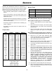
Torque Chart
Service Tools
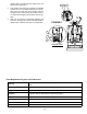
Main Disassembly Procedure (Diesel Engine)
Refer to Main Assembly, page 20. for disassembly.
1. Clean all visible debris from the machine before
servicing.
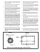
2. Remove the four hex nuts (#31), lock washers (#32)
and washers (#33). Use caution as the engine deck
will drop down.
3. Remove flange head screws (26) and plates (#19)
securing the engine deck (#18) to the baseplate
(#17).
Refer to Diesel Engine Assembly, page 30. Sections of
this manual for belt guard & belt removal, step 3 & 4.
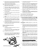
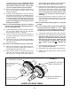
4. Remove the four socket head capscrews (#32)
securing the belt guard (11) to the mount plate (#16)
on the engine (#14) and remove the beltguard.
5. Slide the belt (#3) off the clutch (#6).
6. Remove the two flange screws (#22) securing the
bellows retainer (#11), and remove the retainer.
7. Push the lip of the bellows (#3) through the hole in the
engine deck.
8. Disconnect the hydraulic line (#16) from the control
head in the handle assembly. Keep the end of the
hydraulic line and control head fitting free of dirt and
debris by using tape. Be careful to use a drain pan
to catch the hydraulic oil.
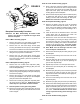
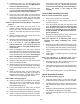
9. Use the main lift hook on the rollcage (#15) to
separate the engine deck from the baseplate. Be
careful to guide the hydraulic line through the
handle assembly and engine deck as the
subassemblies are separated to prevent damage
to components. If further disassembly of the engine
deck is required proceed to step 9. If baseplate
service is required refer to the Baseplate
Disassembly Procedure section of this manual.
10. Disconnect the throttle cable (#14) from the engine.
11. Remove the handle assembly by removing the four
flange screws (#26) securing the handle mount (#4)
to the engine deck (#18).
SIZE GRADE 2 GRADE 5 GRADE 8
1/4-20 49 in
•lbs 76 in•lbs 9 ft•lbs
1/4-28 56 in
•lbs 87 in•lbs 10 ft•lbs
5/16-18 8 ft
•lbs 13 ft•lbs 18 ft•lbs
5/16-24 9 ft
•lbs 14 ft•lbs 20 ft•lbs
3/8-16 15 ft
•lbs 23 ft•lbs 33 ft•lbs
3/8-24 17 ft
•lbs 26 ft•lbs 37 ft•lbs
7/16-14 24 ft
•lbs 37 ft•lbs 52 ft•lbs
7/16-20 27 ft
•lbs 41 ft•lbs 58 ft•lbs
1/2-13 37 ft
•lbs 57 ft•lbs 80 ft•lbs
1/2-20 41 ft
•lbs 64 ft•lbs 90 ft•lbs
9/16-12 53 ft
•lbs 82 ft•lbs 115 ft•lbs
5/8-11 73 ft
•lbs 112 ft•lbs 159 ft•lbs
5/8-18 83 ft
•lbs 112 ft•lbs 180 ft•lbs
3/4-16 144 ft
•lbs 200 ft•lbs 315 ft•lbs
1-8 188 ft
•lbs 483 ft•lbs 682 ft•lbs
1-14 210 ft
•lbs 541 ft•lbs 764 ft•lbs
1-1/2-6 652 ft
•lbs 1462 ft•lbs 2371 ft•lbs
M 6 3 ft
•lbs 4 ft•lbs 7 ft•lbs
M 8 6 ft
•lbs 10 ft•lbs 18 ft•lbs
M 10 10 ft
•lbs 20 ft•lbs 30 ft•lbs
CONVERSIONS
in
•lbs x 0.083 = ft•lbs
ft
•lbs x 12 = in•lbs
ft
•lbs x 0.1383 = kg•m
ft
•lbs x 1.3558 = N•m
Part No. Description
16129 Rubber Test Mat
16031 Decal Set
17368 Kit, Rebuild, Lower Hydraulic
19606 Kit, Rebuild, Upper Hydraulic