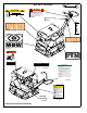
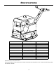
OPERATOR’S SAFETY AND SERVICE MANUAL GPR160 This manual covers the following serial numbers and higher for each model listed: GPR160 . . . . . . . . . . . . . . . . . . 1600001 REVERSIBLE VIBRATORY PLATE MBW, Inc. 250 Hartford Rd • PO Box 440 Slinger, WI 53086-0440 Phone: (262) 644-5234 Fax: (262) 644-5169 Email: mbw@mbw.com Website: www.mbw.com MBW (UK) Ltd. MBW FRANCE S.A.R.L. Units 2 & 3 Cochrane Street Bolton BL3 6BN, England Phone: 01204 387784 Fax: 01204 387797 Z.A.
TABLE OF CONTENTS Safety Information . . . . . . . . . . . . . . . . . . . . . . 1 Introduction . . . . . . . . . . . . . . . . . . . . . . . . . . . . . . . . . 1 Safety Precautions . . . . . . . . . . . . . . . . . . . . . . . . . . . 1 Safety Decals . . . . . . . . . . . . . . . . . . . . . . . . . . . . . . . 1 Service Tools . . . . . . . . . . . . . . . . . . . . . . . . . . . . . . . 8 Main Disassembly Procedure (Diesel Engine) . . . . . . 8 Exciter Oil Change Procedure . . . . . . . . . . . . . . .
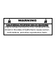
WARNING CALIFORNIA PROPOSITION 65 WARNING Engine exhaust and some of its constituents are known in the state of California to cause cancer, birth defects, and other reproductive harm.
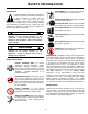
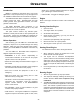
SAFETY INFORMATION Introduction SAFE DRESS: Do not wear loose clothing, rings, wristwatches, etc. near machinery. This Safety Alert Symbol is used to call attention to items or operations which may be dangerous to those operating or working with this equipment. The symbol can be found throughout this manual and on the unit. Please read these warnings and cautions, along with all decals, carefully before attempting to operate the unit.
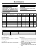
DIESEL MODEL IDLE STOP THROTTLE WARNING CAUTION Machine may fall and cause injury or damage if lifted improperly. All weights shown are with 6” wings. Lift only by lift hook. GPR135H = 878 lbs (398 kg) GPR160H = 906 lbs (411 kg) GPR135DE = 940 lbs (426 kg) GPR160DE = 985 lbs (447 kg) 15853 #15853 RUN 19493 #19493 OPERATION OF THIS EQUIPMENT MAY CREATE SPARKS THAT CAN START FIRES AROUND DRY VEGETATION. A SPARK ARRESTER MAY BE REQUIRED.
SPECIFICATIONS GPR160DE CENTRIFUGAL FORCE 16000 LBF (71 kN) EXCITER (VPM) 3840 vpm TRAVEL SPEED 80 ft./min. (24 m/min.) COMPACTION DEPTH WIDTH x LENGTH OPERATING WEIGHT ENGINE FUEL ENGINE SPEED STARTER SYSTEM OPTIONAL PLATE EXTENSIONS 28 in (71 cm) 25.6 x 37.3 in. (65 x 95 cm) 950 lb. (431 kg) 983 lb. (446 kg) 6” Wings Hatz 1B40 28.2 in.³ (462 cm³) Diesel 3600 rpm Electric Start with Recoil 6 in. (15.
OPERATION Introduction diesel fuel or unleaded gasoline dependent on engine type. (See Engine “Owner’s Manual”) MBW Inc. equipment is intended for use in very severe applications. They are powered by four cycle engines and are available in different sizes and a selection of engines. • FUEL FILTER - If clogged or damaged, replace. Engine The MBW Reversible Plate Compactor is intended to compact various soil types.
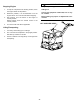
WARNING Stopping Engine 1. To stop the compactor from traveling forward, return the engine throttle to idle position. 2. Whenever possible, it is recommended to let the engine idle for one or two minutes before stopping. 3. Gas engines: Turn the switch on the engine to “STOP” position. Diesel engines: Move the throttle control to the “STOP” position. 4. Turn off the fuel valve where applicable. Always stop the engine before: Adding fuel. Leaving the equipment unattended, even if only for a minute.
MAINTENANCE WARNING CAUTION Always exercise the stopping procedure before servicing or lubricating the unit. Always verify fluid levels and check for leaks after changing fluids. After servicing the unit, replace and fasten all guards, shields, and covers to their original positions before resuming operation. Do not drain oil onto ground, into open streams, or down sewage drains.
4. The engine idle speed must not exceed 1800 RPM. If the idle speed is greater than 1800 RPM the clutch may not disengage. Battery Maintenance 1. 2. Loose or corroded battery terminals will lead to weak starts and poor charging. Clean posts and connectors with a wire brush for best connection. Remove dirt from case using a solution of (2) teaspoons baking soda and (1) pint of water. Dry completely. Always recycle old battery when replacing.
SERVICE Assembly and disassembly should be preformed by a service technician who has been factory trained on MBW equipment. the unit should be clean and free of debris. Pressure washing before disassembly is recommended. • Prior to assembly, wash all parts in a suitable cleaner or solvent. Service Tools • Check moving parts for wear and failure. Refer to the Replacement Section of this manual for tolerances and replacement cycles. Part No.
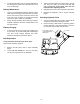
4. Tilt the plate toward a drain pan to aid in the removal of all used oil and particles. 5. Remove the socket head pipe plug (#28) from the baseplate and drain the oil. Examine the oil for metal chips as a precaution to future troubles. 6. 15. Disconnect the negative “black” battery cable (#9) from the batter (#22). Tip the plate opposite the drain hole, and fill the baseplate through the pipe plug opening with exciter oil to level specified in the Fluid Levels section of this manual.
25. Lower engine deck to level position and tighten hex nuts (#31). not to scratch the inner diameter sealing surface of the shift spool when removing the seals. 10. Remove the four flanged capscrews (#21), the cylinder cover (#19) and the cylinder gasket (#18). Be sure to remove all of the gasket pieces from the hydraulic housing to provide a good seal surface for the new gasket. Bleeding And Adjustment of Hydraulic Controls Refer to figure 2 on next page. 11.
Refer to Lower Shaft Assembly, page 24. 11. Place a shop rag under the hydraulic housing (#16) to catch the oil and remove the four flange screws (#22) securing the cylinder mount plate (#20) to the input shaft cover (#12) and remove the hydraulic housing (#16) from the baseplate. ),*85( 12. Remove the shift spool (#15) from the shift shaft (#10) by sliding the shift spool out of the baseplate and holding it secure while unthreading the shift spool. NOTE: This connection is left hand thread.
13. Remove bearings (#14) from handle tube (#8). 26. Note: performance of the following steps will require replacement of the ball bearings (#3). M-B-W recommends replacement of these bearings as a set at every complete disassembly or rebuild. 27. Remove the internal retaining ring (#8) from the helix pin carrier (#9) and remove the shift shaft (#10) and bearings (#3) as a subassembly from the carrier. 28. Remove the e-clip retaining ring (#5) securing the bearings to the shift shaft. 14.
5. Install the hex head screws (#23) and washer (#26) into the shaft bearing covers using LOCTITE #243 thread locker sealant. 13. Install the breather (#3) into the 90 (#2) degree fitting. Make sure breather is clean, functioning & air can pass thru, if unsure replace breather. 6. Install the plastic plugs (#1) in the threaded holes used to press the covers out of the baseplate. 7. Install the key (#12) into the idler shaft (#8). 8.
exciter weights (both weights in the down position) See the figure #5 for setting the gear timing. torque the screws to 13 ft.-lbs. See the figure #3 for LOCTITE #515 gasket maker application. Check input shaft for minimum of .020” end play after covers are installed and the bolts are torqued. 29. Install the other exciter weight (#21) to the input shaft (#16) with two socket head cap screws (#27) using LOCTITE #243 thread locker sealant on the threads and torque the cap screws to 30 ft.-lbs.
to the hydraulic side of the baseplate with the four hex head flange screws (#21). Set the side cover (#12) off to the side until bleeding and final assembly is done. The exciter is now ready for final assembly. 36. Lubricate the inside of the hydraulic housing (#16) and the seal lips with hydraulic oil. See Maintenance section for hydraulic fluid type. 37. Install the hydraulic housing over the hydraulic seals and guide ring. Be careful not to damage the guide ring and hydraulic seals during installation.
5. Install control shaft (#20) into handle tube (#8) and secure with retaining rings (#5). Note: Control shaft can be install for either right or left hand operation. 7. Place battery (#22) into battery box and secure with j-bolts (#5), bracket (#21), washers (#26) and lock nuts (#25). 8. Reinstall positive battery cable to positive post of battery. Reinstall negative battery cable to negative post of battery. 6.
throttle cable in bracket (#5) then tighten jam nuts (#6) after final adjustment. 2. Push throttle control lever (#1) forward to full throttle position (do not force). While holding lever in this position screw in throttle stop set screw (#2) until you can feel it touch or start moving the throttle control lever. Assemble and tighten jam nut (#3) to lock this position. 3. Start unit up and test for full throttle operation and shut down.
Troubleshooting SYMPTOM Engine does not start or stalls. Engine does not accelerate, is hard to start or runs erratically. Engine over heats or runs hot. Engine runs at full speed but machine does not move. Slow or no forward travel speed. REPAIR 1. Fuel valve is closed, open valve (gasoline engine). 2. Engine switch is in “STOP” position, turn switch to “ON” position (gasoline engine). 3. Fouled spark plug, clean or replace spark plug (gasoline engine). 4.
REPLACEMENT PARTS The warranty is stated in this book on page 32. Failure to return the Warranty Registration Card renders the warranty null and void. MBW has established a network of reputable distributors/ dealers with trained mechanics and full facilities for maintenance and rebuilding, and to carry an adequate parts stock in all areas of the country. Their sales engineers are available for professional consultation.
Main Assembly - 20 -
ITEM 1. 2. 3. 4. 5. 6. 7. 8. 9. 10. 11. 12. 13. 14. 15. 16. 17. 18. 19. 20. 21. 22. 23. 24. 25. 26. 27. 28. 29. 30. 31. 32. 33. PART NO.
6(( /2:(5 6+,)7 $66(0%/< 3$*( Baseplate Assembly - 22 -
ITEM 1. 2. 3. 4. 5. 6. 7. 8. 9. 10. 11. 12. 13. 14. 15. 16. 17. 18. 19. 20. 21. 22. 23. 24. 25. 26. 27. 28. 29. PART NO.
Lower Shaft Assembly - 24 -
ITEM 1. 2. 3. 4. 5. 6. 7. 8. 9. 10. 11. 12. 13. 14. 15. 16. 17. 18. 19. 20. 21. 22. PART NO. 05559 16228 16230 19434 16237 16238 16239 16240 16241 16242 16254 16264 16446 17023 17275 17276 17277 17278 17279 17280 F042004FWS F051508FWS 17368 DESCRIPTION CAPPLUG ROLLER BEARING, 100 x 45 BALL BEARING GUIDE RING EXTERNAL RETAINING RING, METRIC HYDRAULIC SEAL WASHER, SHIM INTERNAL RETAINING RING HELIX PIN CARRIER SHIFT SHAFT DOWEL PIN, M10 x 70 BEARING COVER, EXCITER FITTING.
Handle Assembly - 26 -
ITEM 1. 2. 3. 4. 5. 6. 7. 8. 9. 10. 11. 12. 13. 14. 15. 16. 17. 18. 19. 20. 21. 22. 23. 24. 25. 26. 27. 28. PART NO. 11162 16410 16493 17058 17177 17402 19268 19411 19412 19414 19415 19416 19417 19418 19419 19420 19422 19442 19519 19526 19533 F023204FSS F0232HN F02LW F042004FWS F0420ELN F04PW F051804FWS DESCRIPTION SCREW, 1/4 x 1.00, TEKS THREADED ROD, 1/2-13 x 3.00, PLATED HANDLE BUMPER TUBE CAP, ROUND RETAINING RING, EXTERNAL, 1.
Control Head Assembly - 28 -
ITEM 1. 2. 3. 4. 5. 6. 7. 8. 9. 10. 11. 12. 13. 14. 15. 16. PART NO. 08355 16359 16404 16468 16519 17250 19427 19430 19431 19433 19434 19527 19528 19529 F0227SPP F1214SPP DESCRIPTION HYDRAULIC FITTING WASHER SEALING, METRIC O-RING, METRIC, 30mm I.D.
Diesel Engine Assembly - 30 -
ITEM 1. 2. 3. 4. 5. 6. 7. 8. 9. 10. 11. 12. 13. 14. 15. 16. 17. 18. 19. 20. 21. 22. 23. 24. 25. 26. 27. 28. 29. 30. 31. 32. 33. 34. 35. 36. 37. PART NO.
WARRANTY WHAT DOES THIS WARRANTY COVER? MBW, Incorporated (MBW) warrants each New Machine against defects in material and workmanship for a period of twelve (12) months. "New Machine" means a machine shipped directly from MBW or authorized MBW dealer to the end user. This warranty commences on the first day the machine is sold, assigned to a rental fleet, or otherwise put to first use. MBW warrants each Demonstration Machine against defects in material and workmanship for a period of six (6) months.
NOTES: 33
NOTES: 43