
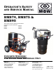
User guide

- 6 -
SERVICE
Assembly and disassembly should be performed by a
service technician who has been factory trained on MBW
equipment. The unit should be clean and free of debris.
Pressure washing before disassembly is recommended.
• Prior to assembly, wash all parts in a suitable cleaner or
solvent.
• Check moving parts for wear and failure. Refer to the
Replacement section in this manual for tolerance and
replacement cycles.
• All shafts and housings should be oiled prior to pressing
bearings. Also, ensure that the bearings are pressed
square and are seated properly.
• All gaskets and seals should be replaced after any
disassembly.
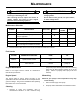
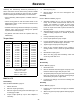
Torque Chart
BMS 74 & 75
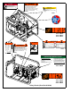
Disassembly
Refer to BMS74 & BMS75, page 10.
1. Detach all hoses.
2. Remove coupler guard (# 2)
3. Remove engine mounting bolts and slide engine out
to disengage coupler.
4. Inspect coupler spider (# 13) for wear. Replace if
necessary.
5. Remove pump (# 7).
6. Remove fittings. Use care not to damage the soft
brass threads.
Assembly
Refer to BMS74 & BMS75, page 10.
1. Assemble couplers (# 11, # 12) on to Engine and
Pump. End of shafts should be flush with front of
coupler. Use antisieze on shafts to insure easy
maintenance in the future. Apply medium strength
Loctite to coupler set screws to prevent screws from
becoming loose.
2. Assemble fittings to pump as shown in diagram. Use
a thread sealing compound on threads to prevent
leaks.
3. Loosely assemble pump to frame.
4. Insert coupler spider into pump coupler.
5. Loosely assemble engine to frame. Take care to align
coupler halves to avoid damage to the spider.
6. Tighten engine and pump mounting bolts.
7. Check for any excessive binding in the coupler by
rotating shafts. If found, correct the problem before
use.
8. Reinstall the coupler guard.
9. When first using pump after assembly, check and
correct any leaks that occur.
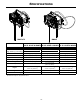
BMS 95
Disassembly
Refer to BMS 95, page 12.
1. Detach all hoses
2. Remove hardware that hold engine and pump to the
frame and remove engine and pump as a unit.
3. To separate pump from engine, remove the (4) socket
head cap screws from the pumps mounting flange
and slide the pump of the engine shaft.
4. If removing any fittings, use care not to damage soft
brass threads.
Assembly
Refer to BMS 95, page 12.
1. Press key into engine shaft and apply an antiseize
compound.
2. Slide the engine and pump together after aligning the
keyways.
SIZE GRADE 2 GRADE 5 GRADE 8
1/4-20 49 in
•lbs 76 in•lbs 9 ft•lbs
1/4-28 56 in
•lbs 87 in•lbs 10 ft•lbs
5/16-18 8 ft
•lbs 13 ft•lbs 18 ft•lbs
5/16-24 9 ft
•lbs 14 ft•lbs 20 ft•lbs
3/8-16 15 ft
•lbs 23 ft•lbs 33 ft•lbs
3/8-24 17 ft
•lbs 26 ft•lbs 37 ft•lbs
7/16-14 24 ft
•lbs 37 ft•lbs 52 ft•lbs
7/16-20 27 ft
•lbs 41 ft•lbs 58 ft•lbs
1/2-13 37 ft
•lbs 57 ft•lbs 80 ft•lbs
1/2-20 41 ft
•lbs 64 ft•lbs 90 ft•lbs
9/16-12 53 ft
•lbs 82 ft•lbs 115 ft•lbs
5/8-11 73 ft
•lbs 112 ft•lbs 159 ft•lbs
5/8-18 83 ft
•lbs 112 ft•lbs 180 ft•lbs
CONVERSIONS
in
•lbs x 0.083 = ft•lbs
ft
•lbs x 12 = in•lbs
ft
•lbs x 0.1383 = kg•m
ft
•lbs x 1.3558 = N•m