OPERATOR’S SAFETY AND SERVICE MANUAL BLITZSCREED CONCRETE SCREEDS MBW, Inc. MBW (UK) Ltd. 250 Hartford Rd • PO Box 440 Slinger, WI 53086-0440 Phone: (262) 644-5234 Fax: (262) 644-5169 Email: mbw@mbw.com Website: www.mbw.com Units 2 & 3 Cochrane Street Bolton BL3 6BN, England Phone: 01204 387784 Fax: 01204 387797 L2335 / 08.06.H ©MBW, Inc.
TABLE OF CONTENTS SAFETY PRECAUTIONS . . . . . . . . . . . . . . . . . . . . . . . . . . . . . . . . . . . . . . . . . 1 INTRODUCTION . . . . . . . . . . . . . . . . . . . . . . . . . . . . . . . . . . . . . . . . . . . . . . . . . 2 SAFETY NOTICE & DECALS . . . . . . . . . . . . . . . . . . . . . . . . . . . . . . . . . . . . . 3 SAFETY DECAL LOCATIONS . . . . . . . . . . . . . . . . . . . . . . . . . . . . . . . . . . . . . 5 WARRANTY . . . . . . . . . . . . . . . . . . . . . . . . . . . . . . . .
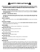
SAFETY PRECAUTIONS READ AND STUDY THE FOLLOWING SAFETY INFORMATION BEFORE ATTEMPTING TO OPERĆ ATE THIS EQUIPMENT. IN ADDITION, ENSURE THAT EVERY INDIVIDUAL WHO OPERATES OR WORKS WITH THIS EQUIPMENT IS FAMILIAR WITH THESE SAFETY PRECAUTIONS. WARNING – LETHAL EXHAUST GAS! An internal combustion engine discharges carbon monoxide, a poisonous, odorless invisible gas. Death or serious illness may result if inhaled.
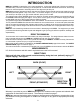
INTRODUCTION MBW Inc. SCREED is intended for use in many applications. It offers the highest level of finishing consistency available today. Precision machining of all components, combined with all bolted construction, are the key factors for ease and speed of assembly and for true alignment job after job. MBW Inc's exclusive 45 degree AĆframe cast aluminum design assures that all sections are exactly the same and totally interchangeable.
SAFETY NOTICE & DECALS IMPORTANT NOTICE The SAFETY ALERT SYMBOL" is used to call attention to items or operations that may be dangerous to machine operators or others working with this equipment. The symbol can be found throughout this manual and on the unit itself. Please read these messages carefully. READ SAFETY DECALS CAREFULLY Carefully read and follow all safety decals. Keep them in good condition. If decals become damaged, replace as required.
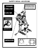
Decals shown below are located only on the hydraulic winches. AUTO STOP MUST BE ADJUSTED EACH TIME SCREED LENGTH OR OPERATING CONDITIONS CHANGE. SET TRAVEL SPEED, THEN INCREASE OR DECREASE AUTO STOP RESISTANCE TO A POINT SLIGHTLY HIGHER THAN REQUIRED TO MAINTAIN DESIRED TRAVEL SPEED.
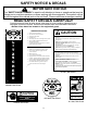
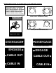
SAFETY DECAL LOCATIONS MĆBĆW ÎÎÎ INC. 1060E #01060E, On Belt Guard #08875, On Belt Guard CAUTION WEAR EYE PROTECTION WHEN OPERATING EQUIPMENT 15459 #15459, On Belt Guard ą 09095 L I T Z S C R E E D PIECES ROTATIVES Ne pas toucher! ROTATING PARTS Keep hands away! 11640 #11640, On Belt Guard CAUTION Read the operating instructions before operating this piece of equipment. Keep unauthorized, inexperienced, untrained people away from this equipment. CHECK saftey switch frequently for proper operation.
SAFETY DECAL LOCATIONS AUTO STOP MUST BE ADJUSTED EACH TIME SCREED LENGTH OR OPERATING CONDITIONS CHANGE. SET TRAVEL SPEED, THEN INCREASE OR DECREASE AUTO STOP RESISTANCE TO A POINT SLIGHTLY HIGHER THAN REQUIRED TO MAINTAIN DESIRED TRAVEL SPEED.
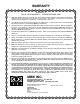
WARRANTY WARRANTY THIS IS YOUR WARRANTY - PLEASE READ AND SAVE 1. MBW INC, Slinger Wisconsin, warrants each new machine against defects in material and workmanship under normal use and service for a period of six (6) months. This warranty commences the first day the machine is sold, assigned to a rental fleet, or otherwise put to first use. 2. The obligation under this warranty is limited to the replacement or repair of parts and/or machine at MBW INC factory branches or at authorized MBW INC Distributors.
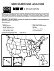
MBW WAREHOUSE LOCATIONS is at your service MBW Inc. has established a network of reputable Distributors with trained mechanics and full facilities for maintenance and rebuilding, and to carry an adequate parts stock in all areas of the country. Their sales engineers are available for professional consultation. If you cannot locate an MBW Inc. Distributor in your area, contact one of our Sales Branches or MBW Inc. The locations and phone numbers of the Sales Branches are listed below.
BLITZSCREED SPECIFICATIONS Mechanical Air Powered Section Length Section Length Model Section Length Model Section Length MVS8 . . . . . . . . . . . . . . . . . . 8 ft. 4 in. (2.54 m) MVS4 . . . . . . . . . . . . . . . . . . 4 ft. 4 in. (1.32 m) MVS2 . . . . . . . . . . . . . . . . . . 2 ft. 4 in. (0.71 m) AVS8 . . . . . . . . . . . . . . . . . . 8 ft. 4 in. (2.54 m) AVS4 . . . . . . . . . . . . . . . . . . 4 ft. 4 in. (1.32 m) AVS2 . . . . . . . . . . . . . . . . . . 2 ft. 4 in. (0.
SERIAL NUMBER LOCATION SCREED AND HYDRAULIC WINCH SERIAL NUMBERS The serial number for each screed section is located on the side of the left most A-Frame. The serial number is also stamped into the top of each A-Frame. SCREED FRAME HYDRAULIC WINCH SERIAL# (Stamped) SERIAL# DECAL PARTS ORDERING PROCEDURE The Warranty is stated in this book on page 7. Failure to return the Warranty Registration Card renders the Warranty null and void. PARTS ORDERING: MBW Inc.
SECTION ASSEMBLY GENERAL The following describes the assembly procedure of screed sections for both Mechanical and Air Screeds. Most figures shown are of a Mechanical Screed. Section assembly of an Air Screed is identical except where otherwise stated. It is essential to follow the proper set-up sequence when assembling the screed for optimum performance. IMPORTANT! For steps 1-10, the screed sections must be on a flat surface. 1.
8. Make sure the bottom of the four edgĆ ings are in the same plane. Tighten both splice plates hard. 9. Take a right turnbuckle eye and install a right-hand jam nut about three quarĆ ters of the way up the shaft. Now install the eye onto the turnbuckle a little over half way. Do the same with the left turnĆ buckle eye (see Figure 8). FIGURE 4 FIGURE 8 FIGURE 5 10.
REPEAT STEPS 6 - 10 UNTIL ENTIRE SCREED IS ASSEMBLED. After all needed sections are assembled the edging can be trued horizontally. 11. If the pour surface is to be crowned or flat, rotate the turnbuckles so the turnĆ buckle eyes are pushed away from each other taking out the slack at the clevis connections. If the pour surface is a valley, rotate the turnbuckles so the turnbuckle eyes are drawn towards each other taking out the slack at the clevis connections (see Figure 10).
ENGINE ASSEMBLY GENERAL The engine can be put on any mechanical screed section on the left end where there are bearings in two adjacent A-frames. ing bracket thru holes aligned above (See Figure 15). These bolts replace the original 3/8-16 X 2 bolts that were removed earlier. 1. To install sheave, first remove left couĆ pling driver. Support end of shaft when driving out the spiral pin. Now remove left end A-frame and clevis. Slide #09126 sheave onto main shaft.
7. Adjust belt tension by sliding engine mounting deck upward in slots. Check belt tension by pinching belt between your fingers. Single Belt - The two sides of the belt should touch or go slightly past each other (see Figure 19). Dual Belt - A 2" gap should remain beĆ tween the two sides of both belts. Tighten the four whiz-lock bolts holding the engine mounting deck to the mounting bracket. NOTE: Do not over tighten belt. FIGURE 17 5. Slip one V-belt over engine clutch.
END FRAME ASSEMBLY GENERAL The end frames are symmetrical and can be used on either end. NOTE: The end frames for the hydraulic drive are left hand and right hand. 1. Set an end frame on one of the screed ends and align the two bottom holes with the two holes in the edging. SeĆ cure with two 3/8-16 X 1 whiz-lock screws and two flange nuts (see Figure 21). 2. Attach eye bolt to clevis and place thru hole in center of cross brace.
HYDRAULIC DRIVE ASSEMBLY 4. Make sure the bottom of the four edgĆ ings are in the same plane. Securely tighten both splice plates. 1. Install end frames on either end of screed. 2. Install a three bolt splice plate on the inĆ side of the float edging. Install a four hole splice plate on the outside of the float edging and loosely install three blind nuts. (see Figure 23) 3. Install a four bolt splice plate on the outĆ side of the strikeoff edging.
OPERATING INSTRUCTIONS INTRODUCTION MBW Inc. Compaction Equipment is intended for use in very severe applications. They are powered by four cycle engines and are available in different sizes and a selection of engines. This parts manual contains only standard or standard option parts. Variations of these parts as well as other special parts are not included. Contact your local MBW, Inc. Distributor for assistance in identifying parts not included in this manuĆ al.
HYDRAULIC OIL SUPPLY - For Screeds with hydraulic winch kits, check to ensure there is an ample supply of Hydraulic Oil in the tank. DRIVE GEAR LEVER - For Screeds with hydraulic winch kits, check to enĆ sure lever is in the disengaged position, before starting the engine. STARTING 1. Open fuel valve. 2. Move choke control to the closed posiĆ tion. A warm engine may not need to be choked. DO NOT START OR RUN THIS MAĆ CHINE IN AN ENCLOSED AREA. THE ENGINE PRODUCES CARBON MONĆ OXIDE, A POISONOUS GAS.
4. Before starting up again, pick up screed and set it back about a foot, then proceed. 5. If there is a time delay between conĆ crete trucks, the unfinished concrete should be rough graded back and well below screed strike off height. This will prevent a cold joint when screed operaĆ tion is resumed. FIGURE 25 CLEANING 1. After using screed for the day, immediĆ ately wash the screed down with a waĆ ter hose or high pressure washer and scrub any hard buildup of concrete with a stiff brush.
SCREED MAINTENANCE & SERVICE A-FRAME REPLACEMENT Make sure offset of coupling driver matches offset of eccentric bearings when installed (thick side of couĆ pling driver matches orientation of thick side of eccentric bearings). Support end of shaft when driving the spiral pin through. The pin should be driven in so an equal amount of the pin is protruding from the coupling driver on either side. 12. If applicable, tighten drive pulley and align as described in ENGINE ASĆ SEMBLY. REMOVAL (Mechanical) 1.
BEARING REPLACEMENT (Mechanical Screed) 1. Remove A-frame (Refer to section on A-FRAME REPLACEMENT). 2. Knock out or press out old bearing out of A-frame. 3. Press new bearing into A-frame. 4. Install A-frame into screed (refer to AFRAME REPLACEMENT). DRIVE BELT REPLACEMENT (Mechanical Screed) GENERAL There should always be two drive belts on the screed. One for driving and one for emerĆ gency replacement. It is assumed the engine kit is installed on the left side of screed for this procedure. 1.
LONG STORAGE (Mechanical Screed) Before storing screed for an extended period of time: 1. Grease bearings with one shot of low temperature grease after final usage before storĆ ing. Run screed at operating speed for one minute after greasing all bearings. 2. Refer to engine's OPERATORS MANUAL for instructions on storage procedure for enĆ gine. CHANGE HYDRAULIC OIL (Hydraulic Winches) 1. Remove winch assembly from screed sections. 2.
BEARING LOCATIONS (MECHANICAL SCREED) The eccentric bearings are located in the screed A-frames as shown below.
AIR EXCITER & GROMMET LOCATIONS (AIR SCREED) Air exciters and grommets are located on the screed as shown below.
26
FIGURE 26: MODEL MVS2 2 1 19 20 6 19 5 12 18 17 9 26 27 10 23 27 25 21 24 14 3 22 4 8 15 7 30 11 18 31 15 14 16 13 29 32 30 17 15 28 16
MODEL MVS2 MVS SCREED SECTION ITEM NO. PART NO. 1 2 3 4 08850 F061616HCS F06LW F0616HN 08841 5 6 7 8 9 10 11 12 13 14 15 16 17 18 19 20 21 22 23 24 25 26 27 28 29 30 31 32 ACCESSORIES, KITS & ASSEMBLIES DESCRIPTION TUBE, TOP 2 FT.
FIGURE 27: MODEL MVS4 19 12 1 18 16 15 2 17 10 20 29 23 27 19 5 14 9 13 26 11 25 24 21 4 22 3 13 8 30 6 15 7 31 14 18 16 13 32 29 17 15 30 28
MODEL MVS4 MVS SCREED SECTION ITEM NO. PART NO. 1 2 3 4 08851 F061616HCS F06LW F0616HN 08841 5 6 7 8 9 10 11 12 13 14 15 16 17 18 19 20 21 22 23 24 25 26 27 28 29 30 31 32 ACCESSORIES, KITS & ASSEMBLIES DESCRIPTION TUBE, TOP 4 FT.
FIGURE 28: MODEL MVS8 1 19 1 18 15 2 17 12 16 10 20 19 12 9 13 26 31 27 14 5 23 11 25 24 4 3 13 8 30 6 15 7 31 11 16 14 18 13 32 29 15 17 30 28
MODEL MVS8 MVS SCREED SECTION ITEM NO. PART NO. 1 2 3 4 08852 F061616HCS F06LW F0616HN 08841 5 6 7 8 9 10 11 12 13 14 15 16 17 18 19 20 21 22 23 24 25 26 27 28 29 30 31 32 ACCESSORIES, KITS & ASSEMBLIES DESCRIPTION TUBE, TOP 8 FT.
7 2 6 5 1 4 3 22 29 31 8 31 17 32 18 33 9 16 30 10 24 11 13 25 14 31 26 15 23 12 28 32 24 12 12 33 27 12 21 11 19 20 When using screeds exceeding 40’ in length, MBW Inc. recommends the use of the 8hp engine. On all hydraulic screeds MBW Inc. recommends the use of the 8hp engine.
5.5 HP HONDA ENGINE KIT PART NUMBER 08881 ITEM NO PART NO 1 2 3 4 5 6 7 8 9 10 11 12 13 14 15 16 17 18 19 20 21 22 23 24 25 26 27 28 29 30 31 32 33 01444 06473 00032 F052412HCS F05LW 01099 09071 F051812HCS F05SW F0518FN F061608FWS F0616FN F061620HCS F06LW 09090 09087 09092 F051804FWS 09126 09076 11734 08808 08829 F1216HN F12LW F101818HCS F10LW F1018HN 08885 F081310HCS F08SW F08LW F0813HN DESCRIPTION QTY ENGINE, HONDA GX160K1QX CLUTCH, CENTRIFUGAL 3/4 BORE KEY, 3/16 sq.
5.0 HP BRIGGS & STRATTON ENGINE KIT PART NUMBER 08855 ITEM NO PART NO 1 2 3 4 5 6 7 8 9 10 11 12 13 14 15 16 17 18 19 20 21 22 23 24 25 26 27 28 29 30 31 32 33 01304 06473 00032 F052412HCS F05LW 01099 09071 F051812HCS F05SW F0518FN F061608FWS F0616FN F061620HCS F06LW 09090 09087 09092 F051804FWS 09126 09076 11734 08808 08829 F1216HN F12LW F101818HCS F10LW F1018HN 08885 F081310HCS F08SW F08LW F0813HN DESCRIPTION QTY ENGINE, BRIGGS & STRATTON 135232 5.0 H.P. CLUTCH, CENTRIFUGAL 3/4 BORE KEY, 3/16 sq.
8.0 HP HONDA ENGINE KITS ITEM 1. 2. 3. 4. 5. 6. 7. 8. 9. 10. 11. 12. 13. 14. 15. 16. 17. 18. 19. 20. 21. 22. 23. 24. 25. 26. 27. 28. 29. 30. 31. 32. 33. PART NO. 01465 06606 17149 01161 F072012HCS F07LW 06638 09096 F061614HCS F06SW F0616FN F061608FWS F0616FN F061620HCS F06LW 09090 09087 09092 F051804FWS 09126 16272 09076 11734 08808 08829 F1216HN F12LW F101818HCS F10LW F1018HN 08885 F081310HCS F08SW F08LW F0813HN 09072 16273 DESCRIPTION ENGINE, HONDA GX240K1QA 8 H.P.
FIGURE 30: MODEL AVS2 37 20 21 26 12 19 23 27 25 22 16 12 26 15 18 17 28 24 31 29 23 11 30 13 5 33 1 34 12 32 7 2 6 3 13 4 9 10 15 11 8
MODEL AVS2 AVS SCREED SECTION ITEM NO. PART NO. 1 2 3 4 5 6 7 8 9 10 11 12 13 15 16 17 18 19 20 21 22 23 24 25 26 27 28 29 30 31 32 33 34 08850 F061616HCS F06LW F0616HN 08805 08806 08870 08846 08871 F061608FWS F061614FWS 08818 08912 08828 F101818HCS F10LW F1018HN 08839 08830 F1216HJN-LH 08829 F1216HJN 08831 08832 08838 08905 08894 F12LW 08900 F061607FWS F0616FN 09074 08909 DESCRIPTION TUBE, TOP 2 FT.
FIGURE 31: MODEL AVS4 39 20 26 12 21 19 27 25 23 22 16 12 26 17 18 15 24 11 28 13 5 10 29 23 4 34 3 13 2 32 30 1 10 33 29 23 14 12 31 7 28 6 9 10 15 11 8
MODEL AVS4 AVS SCREED SECTION ITEM NO. PART NO. 1 2 3 4 5 6 7 8 9 10 11 12 13 14 15 16 17 18 19 20 21 22 23 24 25 26 27 28 29 30 31 32 33 34 08851 F061616HCS F06LW F0616HN 08805 08806 08870 08847 08872 F061608FWS F061614FWS 08818 08877 F0227SPP 08828 F101818HCS F10LW F1018HN 08839 08830 F1216HJN-LH 08829 F1216HJN 08831 08832 08838 08905 08894 F12LW 08900 F061607FWS F0616FN 09074 08909 DESCRIPTION TUBE, TOP 4 FT.
FIGURE 32: MODEL AVS8 41 20 21 26 12 19 23 27 25 22 16 12 26 17 18 15 24 4 11 3 2 13 5 7 14 10 13 6 30 32 34 33 1 10 31 28 23 29 12 31 13 7 28 13 9 10 15 8 11
MODEL AVS8 AVS SCREED SECTION ITEM NO. PART NO. 1 2 3 4 5 6 7 8 9 10 11 12 13 14 15 16 17 18 19 20 21 22 23 24 25 26 27 28 29 30 31 32 33 34 08852 F061616HCS F06LW F0616HN 08805 08806 08870 08848 08873 F061608FWS F061614FWS 08818 08902 F0227SPP 08828 F101818HCS F10LW F1018HN 08839 08830 F1216HJN-LH 08829 F1216HJN 08831 08832 08838 08905 08894 F12LW 08900 F061607FWS F0616FN 09074 08909 DESCRIPTION TUBE, TOP 8 FT.
FIGURE 33: AIR REGULATOR KIT 43 1 2 12 3 10 7 9 14 13 5 15 6 4 16 2 2 17 7 2 4 7 11 8 22 17 24 23 18 8 19 20 22 21
AIR REGULATOR KIT PART NUMBER 08915 ITEM NO PART NO 1 2 3 4 5 6 7 8 9 10 11 12 13 14 15 16 17 18 19 20 21 22 23 24 08983 01590 08910 01591 08901 01223 F061608FWS F0616FN F051807FWS F0518FN 08911 08916 F101818HCS F10LW F1018HN 08829 F1216HN F12LW 08808 08885 F081310HCS F10SW F08LW F0813HN DESCRIPTION QTY VALVE, BALL NIPPLE, BLACK PIPE, 1 X 3 REGULATOR UNIT, COMBINATION FITTING, PIPE 90° X 1" BRACKET, MOUNTING PIPE RING FWLS, 3/8-16 X 1 NUT, FLANGE WHIZ-LOCK 3/8-16 FWLS, 5/16-18 X 7/8 NUT, FLANGE WHIZ-L
7 3 9 8 3 6 12 1 13 14 15 7 3 6 12 5 4 2 7 10 3 6 11 FIGURE 34: HAND WINCH KIT 45 13 (Two Winches One End) 5 2
FIGURE 35: HAND WINCH KIT (One Winch Each End) 1 3 2 3 4 2 5 6 7 HAND WINCH KIT PART NUMBER 08858 ITEM NO PART NO 1 2 3 4 5 6 7 8 9 10 11 12 13 14 15 16186 F061608FWS F0616FN 08976 08993 08891 08888 09065 F06SW F061612FWS F0616DLN 01428 F061606FWS 16185 15336 DESCRIPTION QTY WINCH, L.H.
FIGURE 36-1:HYDRAULIC WINCH KIT (LH SHOWN) 47
HYDRAULIC WINCH ITEM NO PART NO DESCRIPTION QTY 1 08808 WELDMENT, BRACKET END 1 2 14722 CLEVIS, THREADED 1 3 15318 TANK, OIL, SCREED 1 4 15336 HANDLE WINCH 1 5 15345 WINCH DRIVE ASSEMBLY (L.H.
FIGURE 36-2: HYDRAULIC WINCH KIT (LH SHOWN) 49
HYDRAULIC WINCH ITEM NO PART NO 1 08808 WELDMENT, BRACKET END 1 2 08818 NUT, BLIND 7 3 08831 PLATE, ASSEMBLY, SPLICE (4 BOLT) 1 4 08838 PLATE, SPLICE 2 5 08942 BRACKET, MOUNTING 1 6 09739 KEY,1/8 SQ x .
FIGURE 36-3:HYDRAULIC WINCH KIT (LH SHOWN) 51
ITEM 1. 2. 3. 4. 5. 6. 7. 8. 9. 10. 11. 12. 13. 14. 15. 16. 17. 18. PART NO.
FIGURE 37: WINCH ASSEMBLY (LH SHOWN) 53
WINCH ASSEMBLY ITEM PART NO. DESCRIPTION 1. 2. 3. 4. 5. 6. 7. 8. 9. 10. 11. 12. 13. 14.