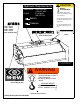
OPERATOR’S SAFETY AND SERVICE MANUAL AT73 AT84 This manual covers the following serial numbers and higher for each model listed: ATS73 . . . . . . . . . . . . . . . . . . . . 4070001 ATP73 . . . . . . . . . . . . . . . . . . . . 4070001 ATS84 . . . . . . . . . . . . . . . . . . . . 4080001 ATP84 . . . . . . . . . . . . . . . . . . . . 4080001 SKID-STEER ROLLER ATTACHMENTS MBW, Inc. MBW (UK) Ltd. MBW France S.A.R.
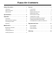
TABLE OF CONTENTS Safety Information . . . . . . . . . . . . . . . . . . . . . . 1 Service. . . . . . . . . . . . . . . . . . . . . . . . . . . . . . . . 7 Introduction . . . . . . . . . . . . . . . . . . . . . . . . . . . . . . . . . 1 Torque Chart . . . . . . . . . . . . . . . . . . . . . . . . . . . . . . . 7 Safety Precautions . . . . . . . . . . . . . . . . . . . . . . . . . . . 1 Service Tools . . . . . . . . . . . . . . . . . . . . . . . . . . . . . . . 7 Safety Decals . . . . . . . . . . . . .
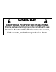
WARNING CALIFORNIA PROPOSITION 65 WARNING Engine exhaust and some of its constituents are known in the state of California to cause cancer, birth defects, and other reproductive harm.
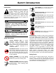
SAFETY INFORMATION Introduction SAFE DRESS: Do not wear loose clothing, rings, wristwatches, etc. near machinery. This Safety Alert Symbol is used to call attention to items or operations which may be dangerous to those operating or working with this equipment. The symbol can be found throughout this manual and on the unit. Please read these warnings and cautions, along with all decals, carefully before attempting to operate the unit.
CAUTION Hydraulic Requirements HEAVY ATTACHMENT PRESSURE: 1500-3000 psi (103-207 bar) FLOW: 10-50 gpm (38-190 l/m) Overloading skid loader could cause loader to pitch or tip forward. Return Check lifting capacity of skid loader before hooking onto attachment. Pressure 17906 - ATS73 17907 - ATP73 17908 - ATS84 17909 - ATP84 (NOT IN DECAL SET) 14435 14435 Do not lift attachment over 12” (30cm) above ground level.
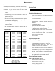
SPECIFICATIONS ATP84 ATS73 ATP73 ATS84 ATP84 Centrifugal Force 8850 lbs (4014 kg) 9765 lbs (4429 kg) Exciter Speed 3000 rpm 3000 rpm Dynamic Linear Force 121 lb/in (21.7 kg/cm) 116 lb/in (20.8 kg/cm) Amplitude - - Length 43.3 in (110 cm) 43.
OPERATION Introduction 4. MBW equipment is intended for use in very severe applications. Lower the roller, and engage the loaders’ arms into their float mode. 5. Engage the auxiliary hydraulics and allow the vibrator to come up to speed. This parts manual contains only standard parts. Variations of these parts as well as other special parts are not included. Contact your local MBW distributor for assistance in identifying parts not included in this manual.
MAINTENANCE WARNING CAUTION Always exercise the stopping procedure before servicing or lubricating the unit. Always verify fluid levels and check for leaks after changing fluids. After servicing the unit, replace and fasten all guards, shields, and covers to their original positions before resuming operation. Do not drain oil onto ground, into open streams, or down sewage drains.
7. Fill exciter with MBW Ground Pounder® Exciter Oil until oil starts to drain from oil check plug. See chart for proper amounts. 2. Remove oil check plug. The plug is the smaller of the two on the vent side which also has an allen head drive. 8. Replace both plugs. 3. Rotate drum until check plug is at 6 o’clock position. 4. If oil level is adequate, it should dribble out of hole. 5. If necasary, remove fill/drain plug, and add MBW Ground Pounder® Exciter Oil. Checking Exciter Oil 1.
SERVICE Service Tools Assembly and disassembly should be performed by a service technician who has been factory trained on MBW equipment. The unit should be clean and free of debris. Pressure washing before disassembly is recommended. • Prior to assembly, wash all parts in a suitable cleaner or solvent. • All shafts and housings should be oiled prior to pressing bearings. Also, ensure that the bearings are pressed square and are seated properly.
4. Installing Exciter Bearings and Shaft. To remove coupler gear (# 15) from exciter shaft will require 07353 clutch removal tool. Turn coupler gear clockwise (left hand threads) to remove. Refer to Drum Assembly, page 12. Installing Drive Coupler 1. Install new bearings (# 8) into housings (# 5 & 14). Use oil on the OD of the bearing and press on the outer race of the bearing. Failure to do so will result in damage to the bearings. Refer to Main Assembly, page 14. 1.
Parts Replacement Cycles and Tolerances Bearings Replace anytime a bearing is rough, binding, discolored or removed from housing or shaft. Hardware Replace any worn or damaged hardware as needed. Replacement hardware should be grade 5 and zinc plated unless otherwise specified. Safety Decals Replace if they become damaged or illegible. Seals & Gaskets Replace if a leak is detected and at every overhaul or tear down.
This page intentionally left blank.
REPLACEMENT PARTS The warranty is stated in this book on page 18. Failure to return the Warranty Registration Card renders the warranty null and void. DECAL MBW has established a network of reputable distributors/ dealers with trained mechanics and full facilities for maintenance and rebuilding, and to carry an adequate parts stock in all areas of the country. Their sales engineers are available for professional consultation.
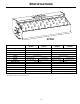
9 10 14 8 18 3 19 13 4 8 20 7 16 6 12 3 19 18 5 7 11 1 2 15 17 Drum Assembly - 12 -
7. 8. 9. 10. 11. 12. 13. 14. 15. 16. 17. 18. 19. 20. ATS84 01072 01191 07011 08188 17807 17911 17811 17913 17813 17844 17845 17846 18111 17853 17854 17858 17859 17938 F0205SP F0418SPP F042005FSS F061604HCS F061610FWS F0618SHPP ATP84 1. 2. 3. 4. 5. 6. DESCRIPTION ATS73 PART NO. ATP73 ITEM FILTER, FELT RETAINING RING, INTERNAL, STAR RETAINING RING, INTERNAL DECAL, EXCITER OIL COVER, EXCITER, BREATHER SIDE DRUM, ATP73 (PADDED) DRUM, ATS73 (SMOOTH) DRUM, ATP84 (PADDED) DRUM, ATS84 (SMOOTH) O-RING, 7.
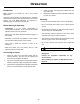
Main Assembly - 14 -
4. 5. 6. 7. 8. 9. 10. 11. 12. 13. 14. 15. 16. 17. 18. 19. 20. 21. 22. 23. 24. 25. 26. 27. 28. 29. 30. 13166 17980 13984 14267 14747 17842 17843 17850 17851 17856 17924 17894 17925 17895 17975 17976 17977 17981 17979 18107 18127 18656 18657 F051836HCS F0518FN F05SW F061607FWS F061610SCS F06LW F081312HCS F08LW F101112HCS F1011HN F10LW 17994 ATS84 08213 08730 ATP84 1. 2. 3. DESCRIPTION ATS73 PART NO. ATP73 ITEM FITTING, STRAIGHT FITTING, ELBOW HOSE, HYDRAULIC 1/2” X 47.
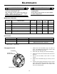
Spider Assembly - 16 -
ITEM PART NO. 1. 2. 3. 4. 5. 6.
WARRANTY WHAT DOES THIS WARRANTY COVER? MBW, Incorporated (MBW) warrants each New Machine against defects in material and workmanship for a period of twelve (12) months. "New Machine" means a machine shipped directly from MBW or authorized MBW dealer to the end user. This warranty commences on the first day the machine is sold, assigned to a rental fleet, or otherwise put to first use. MBW warrants each Demonstration Machine against defects in material and workmanship for a period of six (6) months.