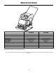
OPERATOR’S SAFETY AND SERVICE MANUAL GP5800 This manual covers the following serial numbers and higher for each model listed: GP5800.................................5800001 VIBRATORY PLATE MBW, Inc. MBW (UK) Ltd. MBW FRANCE S.A.R.L. 250 Hartford Rd • PO Box 440 Slinger, WI 53086-0440 Phone: (262) 644-5234 Fax: (262) 644-5169 Email: mbw@mbw.com Website: www.mbw.com Units 2&3 CochraneStreet Bolton BL3 6BN England, UK Phone: 44 (0) 01204 387784 Fax: 44 (0) 01204 387797 E-mail: mbwuk@btinternet.com Z.A.
TABLE OF CONTENTS Safety Information . . . . . . . . . . . . . . . . . . . . . . 1 Service. . . . . . . . . . . . . . . . . . . . . . . . . . . . . . . . 8 Introduction . . . . . . . . . . . . . . . . . . . . . . . . . . . . . . . . . 1 Torque Chart . . . . . . . . . . . . . . . . . . . . . . . . . . . . . . . 8 Safety Precautions . . . . . . . . . . . . . . . . . . . . . . . . . . . 1 Service Tools . . . . . . . . . . . . . . . . . . . . . . . . . . . . . . . 8 Safety Decals . . . . . . . . . . . . .
WARNING CALIFORNIA PROPOSITION 65 WARNING Engine exhaust and some of its constituents are known in the state of California to cause cancer, birth defects, and other reproductive harm.
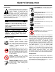
SAFETY INFORMATION Introduction SAFE DRESS: Do not wear loose clothing, rings, wristwatches, etc. near machinery. This Safety Alert Symbol is used to call attention to items or operations which may be dangerous to those operating or working with this equipment. The symbol can be found throughout this manual and on the unit. Please read these warnings and cautions, along with all decals, carefully before attempting to operate the unit.
CAUTION WARNING OPERATION OF THIS EQUIPMENT MAY CREATE SPARKS THAT CAN START FIRES AROUND DRY VEGETATION. A SPARK ARRESTER MAY BE REQUIRED. THE OPERATOR SHOULD CONTACT LOCAL FIRE AGENCIES FOR LAWS OR REGULATIONS 19791 RELATING TO FIRE PREVENTION Machine may fall and cause injury or damage if lifted improperly. Lift by handles or rollcage only.
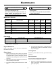
SPECIFICATIONS Centrifugal Force GP5800H GP5800R 5800 lbf (25.8 kN) 5800 lbf (25.8 kN) Exciter Speed 4800 vpm 4800 vpm Travel Speed 130 ft./min. (39.6 m/min.) 130 ft./min. (39.6 m/min.) Compaction Depth 20 in (51 cm) 20 in (51 cm) Plate Size (W x L) 23 x 24 in (58 x 61 cm) 23 x 24 in (58 x 61 cm) Operating Weight 289 lb. (131 kg) 280 lb.
OPERATION Introduction 5. Pull starter rope repeatedly until engine starts. MBW equipment is intended for use in very severe applications. They are powered by four cycle engines and are available in different sizes and a selection of engines. 6. Move choke lever to open position. 7. Allow engine to warm up for one or two minutes. This parts manual contains only standard parts. Variations of these parts as well as other special parts are not included.
MAINTENANCE WARNING CAUTION Always exercise the stopping procedure before servicing or lubricating the unit. Always verify fluid levels and check for leaks after changing fluids. After servicing the unit, replace and fasten all guards, shields, and covers to their original positions before resuming operation. Do not drain oil onto ground, into open streams, or down sewage drains.
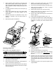
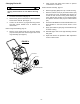
2. Apply moderate thumb pressure to belt about half way between pulleys. When properly adjusted the belt should deflect approximately 3/8” (9mm). If the belt is adjusted correctly reinstall belt guard and hardware. 3. To adjust belt tension loosen (do not remove) the (4) engine bolts. 4. Push engine towards the back of the plate. While holding pressure on the engine retighten the (4) engine bolts. 5.
Changing Exciter Oil 5. Refer to Exciter Assembly, page 12. WARNING Exciter and oil are hot after machine has been running. Allow machine to cool before servicing unit. 1. Let exciter cool before changing oil. 2. Remove belt guard as described in Belt Adjustment section of this manual. (See figure 1) 3. Loosen, do not remove, (4) engine mounting screws and slide engine towards front of machine and remove belt. Refer to Engine Assembly, page 14. 4.
SERVICE Assembly and disassembly should be performed by a service technician who has been factory trained on MBW equipment. The unit should be clean and free of debris. Pressure washing before disassembly is recommended. Service Tools 17320 Ground Pounder® Exciter Oil • Prior to assembly, wash all parts in a suitable cleaner or solvent. 016129 Rubber Test Mat 12100 Decal Set 20190 Service Kit Part No. • Check moving parts for wear and failure.
2. Press front bearing (#9) into exciter housing (#1). 3. Press (#17). 4. Install snap ring (#10) onto exciter shaft, opposite end as pulley. 5. Support I.D. and O.D. of bearing (#9) and press exciter shaft into bearing. 6. Slide pulley off of exciter shaft. be sure not to lose shaft key (#14). Install snap ring (#10) onto exciter shaft on pulley end. 7. Note: To aid in removal of rear cover you will need two 5/1618 bolts, minimum grade 5.
Exciter installation Refer to Exciter Assembly, page 12. 17. Press oil seal (#6) into front cover (#16), Seal to be press in until flush with front cover. Refer to Exciter Assembly, page 12. 1. 19. Install front cover (#16) and 6 flange screws (#22). Torque flange screws to 13 ft.-lbs. Clean exciter mounting bars on bottom plate. If unit was equipped with exciter shims (#3) replace to original position and set exciter assembly in place on mounting bars. 2. 20.
REPLACEMENT PARTS The warranty is stated in this book on page 18. Failure to return the Warranty Registration Card renders the warranty null and void. MBW has established a network of reputable distributors/ dealers with trained mechanics and full facilities for maintenance and rebuilding, and to carry an adequate parts stock in all areas of the country. Their sales engineers are available for professional consultation.
20 24 5 18 12 27 26 10 22 14 21 28 2 21 9 16 8 6 17 15 1 3 13 23 11 19 Exciter Assembly - 12 - 4 10 25 7
ITEM 1. 2. 3. 4. 5. 6. 7. 8. 9. 10. 11. 12. 13. 14. 15. 16. 17. 18. 19. 20. 21. 22. 23. 24. 25. 26. 27. 28. PART NO.
6 1 7 3 10 8 5 13 11 12 9 2 14 4 16 16 Engine Assembly - 14 - 15
ITEM 1. 2. 3. 4. 5. 6. 7. 8. 9. 10. 11. 12. 13. 14. 15. 16. PART NO. 00808 01011 05881 12968 14992 15674 19127 19136 19994 F061616HCS F06LW F06SW F072008FSS F081305HCS F081307HCS M12ETLW 20190 DESCRIPTION SHAFT KEY, 1/4” SQUARE X 1-3/4” lg. SHOCK MOUNT V-BELT, A37 ENGINE MOUNTING BAR WASHER, COUNTERSUNK HONDA ENGINE, GX270 CLUTCH, CENTRIFUGAL SHAFT SPACER ENGINE DECK ASSEMBLY HEX HEAD CAP SCREW, 3/8-16 x 2” LG. LOCKWASHER, 3/8” STANDARD FLAT WASHER, 3/8” FLAT HEAD SOCKET SCREW, 7/16-20 x 1” LG.
9 7 1 3 2 3 15 16 10 6 4 11 12 13 14 8 15 5 16 6 10 ROLLCAGE ASSEMBLY - 16 - 17
ITEM 1. 2. 3. 4. 5. 6. 7. 8. 9. 10. 11. 12. 13. 14. 15. 16. 17. PART NO. 01019 15830 16191 16189 16227 16908 19999 20009 20010 F051806FWS F061608HCS F06LW F06SW F081305HCS F081306HCS F08LW M12ETLW DESCRIPTION HANDLE BUSHING, INNER HANDLE ATTACHMENT NUT HANDLE BUSHING, OUTER SHOCKMOUNT LIFT HANDLE SHOCK MOUNT, HANDLE ROL CAGE, 5800 BELT GUARD HANDEL ASSEMBLY (Includes items #1 & #3) FLANGE HEAD LOCK SCREW, 5/16-18 x 3/4” LG. HEAX HEAD CAP SCREW, 3/8-16 x 1” LG.
WARRANTY WHAT DOES THIS WARRANTY COVER? MBW, Incorporated (MBW) warrants each New Machine against defects in material and workmanship for a period of twelve (12) months. "New Machine" means a machine shipped directly from MBW or authorized MBW dealer to the end user. This warranty commences on the first day the machine is sold, assigned to a rental fleet, or otherwise put to first use. MBW warrants each Demonstration Machine against defects in material and workmanship for a period of six (6) months.