
Manual

- 9 -
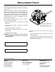
SERVICE
Assembly and disassembly should be performed by a
service technician who has been factory trained on MBW
equipment. The unit should be clean and free of debris.
Pressure washing before disassembly is recommended.
• Prior to assembly, wash all parts in a suitable cleaner or
solvent.
• Check moving parts for wear and failure. Refer to the
Replacement section in this manual for tolerance and
replacement cycles.
• All shafts and housings should be oiled prior to pressing
bearings. Also, ensure that the bearings are pressed
square and are seated properly.
• All bearings should be replaced when rebuilding any
exciter or gearbox.
• All gaskets and seals should be replaced after any
disassembly.
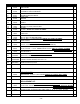
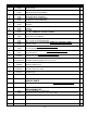
Torque Chart
Service Tools
Exciter Removal
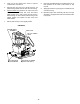
1. Remove roll cage assembly, engine deck assembly
and belt. Refer to Changing Exciter Oil, page 7.
2. Remove 4 5/8-11 exciter bolts, washers, lock
washers and nuts. If unit has exciter shims (7) make
note of location to assure proper placement during
reassembling.
3. Clean exciter and drain oil as described in Changing
Exciter Oil section of this manual before proceeding
with disassembly.
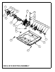
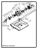
(2000) Exciter Disassembly
Refer to 2000 & 2018 EXCITER ASSEMBLY, page 14.
for exciter disassembly.
1. Remove flange screw (23) and washer (8) securing
the pulley (19) to the exciter shaft (20).
2. Slide pulley off of exciter shaft. be sure not to lose
shaft key (17).
3. Remove 6 flange screws (23) from rear cover plate
(2) and remove cover, opposite of pulley end.
4. Support exciter assembly on outside diameter of
exciter housing (1) and press exciter shaft out of
housing.
5. Remove 6 flange screws (22) from front cover plate
(18) and remove front cover.
Note: If bearings have failed and need to be replace
then proceed with bearing removal steps. If
bearings do not need replacing skip to step #9.
6. Support exciter housing (1) and press out front
bearing (4).
7. Remove front bearing (4) inner race from exciter shaft
by supporting O.D. of race and pressing exciter shaft
thru.
8. Remove snap ring (6) and press rear bearing (5) off
of shaft (20).
9. When reassembling always replace, oil seal (13) and
front & rear cover gaskets (10 & 11).
SIZE GRADE 2 GRADE 5 GRADE 8
1/4-20 49 in
•lbs 76 in•lbs 9 ft•lbs
1/4-28 56 in
•lbs 87 in•lbs 10 ft•lbs
5/16-18 8 ft
•lbs 13 ft•lbs 18 ft•lbs
5/16-24 9 ft
•lbs 14 ft•lbs 20 ft•lbs
3/8-16 15 ft
•lbs 23 ft•lbs 33 ft•lbs
3/8-24 17 ft
•lbs 26 ft•lbs 37 ft•lbs
7/16-14 24 ft
•lbs 37 ft•lbs 52 ft•lbs
7/16-20 27 ft
•lbs 41 ft•lbs 58 ft•lbs
1/2-13 37 ft
•lbs 57 ft•lbs 80 ft•lbs
1/2-20 41 ft
•lbs 64 ft•lbs 90 ft•lbs
9/16-12 53 ft
•lbs 82 ft•lbs 115 ft•lbs
5/8-11 73 ft
•lbs 112 ft•lbs 159 ft•lbs
5/8-18 83 ft
•lbs 112 ft•lbs 180 ft•lbs
3/4-16 144 ft
•lbs 200 ft•lbs 315 ft•lbs
1-8 188 ft
•lbs 483 ft•lbs 682 ft•lbs
1-14 210 ft
•lbs 541 ft•lbs 764 ft•lbs
1-1/2-6 652 ft
•lbs 1462 ft•lbs 2371 ft•lbs
M 6 3 ft
•lbs 4 ft•lbs 7 ft•lbs
M 8 6 ft
•lbs 10 ft•lbs 18 ft•lbs
M 10 10 ft
•lbs 20 ft•lbs 30 ft•lbs
CONVERSIONS
in
•lbs x 0.083 = ft•lbs
ft
•lbs x 12 = in•lbs
ft
•lbs x 0.1383 = kg•m
ft
•lbs x 1.3558 = N•m
Part No. Description
17320 Ground Pounder® Exciter Oil
016129 Rubber Test Mat
12100 Decal Set