OPERATOR’S SAFETY AND SERVICE MANUAL 2000, 2018 AP2000+ & 3550 This manual covers the following serial numbers and higher for each model listed: 2000........................................2064575. 2018........................................2180100. 3550........................................3551200. VIBRATORY PLATES MBW, Inc. MBW (UK) Ltd. MBW FRANCE S.A.R.L. 250 Hartford Rd • PO Box 440 Slinger, WI 53086-0440 Phone: (262) 644-5234 Fax: (262) 644-5169 Email: mbw@mbw.com Website: www.mbw.
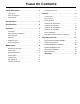
TABLE OF CONTENTS Safety Information . . . . . . . . . . . . . . . . . . . . . . 1 Changing Exciter Oil. . . . . . . . . . . . . . . . . . . . . . . . . . 7 Introduction . . . . . . . . . . . . . . . . . . . . . . . . . . . . . . . . . 1 Service. . . . . . . . . . . . . . . . . . . . . . . . . . . . . . . . 9 Safety Precautions . . . . . . . . . . . . . . . . . . . . . . . . . . . 1 Safety Decals . . . . . . . . . . . . . . . . . . . . . . . . . . . . . . . 1 Specifications. . . . . . . . . . . . . . .
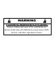
WARNING CALIFORNIA PROPOSITION 65 WARNING Engine exhaust and some of its constituents are known in the state of California to cause cancer, birth defects, and other reproductive harm.
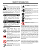
SAFETY INFORMATION Introduction SAFE DRESS: Do not wear loose clothing, rings, wristwatches, etc. near machinery. This Safety Alert Symbol is used to call attention to items or operations which may be dangerous to those operating or working with this equipment. The symbol can be found throughout this manual and on the unit. Please read these warnings and cautions, along with all decals, carefully before attempting to operate the unit.
01066 CAUTION Read the Operating Instructions before operating this piece of equipment. Keep unauthorized and untrained people away from this equipment. ROTATING & MOVING PARTS! Make sure all guards and safety devices are in place. Wear approved hearing protection, foot protection, eye protection and head protection. STOP SHUT OFF the motor before servicing or cleaning. DO NOT RUN in an enclosed area. The engine produces carbon monoxide, a POISONOUS GAS.
SPECIFICATIONS AP2018 $3 AP2000 GP2000 AP2018 GP2018 2475 lbf (1123 kg) 3250 lbf (1474 kg) 2475 lbf (1123 kg) 3250 lbf (1474 kg) EXCITER (VPM) 4400 5050 4400 5050 TRAVEL SPEED 90 ft/min(28 m/min) 120 ft/min(36 m/min) 90 ft/min(28 m/min) 120 ft/min(36 m/min) CENTRIFUGAL FORCE COMPACTION DEPTH 12 in (30 cm) 14 in (36 cm) 12 in (30 cm) 14 in (36 cm) 20 x 22 x 21 in (51 x 56 x 53 cm) 20 x 22 x 21 in (51 x 56 x 53 cm) 20 x 22 x 18 in (51 x 56 x 46 cm) 20 x 22 x 18 in (51 x 56 x 4
SPECIFICATIONS $3 CENTRIFUGAL FORCE AP3550 GP3550 3550 lbf (1610 kg) 3550 lbf (1610 kg) EXCITER (VPM) 4400 4400 TRAVEL SPEED 110 ft/min(34 m/min) 110 ft/min(34 m/min) 18 in (46 cm) 18 in (46 cm) 21 x 22 x 22.2 in (53 x 56 x 56.3 cm) 21 x 22 x22.2 in (53 x 56 x 56.3 cm) 229 lbs (104 kg) no water 254 lbs (115 kg) full water 226 lbs (103 kg) ENGINE SPEED 3400 (RPM) 3400 (RPM) WATER TANK CAPACITY 3 gal (11.
OPERATION Introduction 5. Pull starter rope repeatedly until engine starts. MBW equipment is intended for use in very severe applications. They are powered by four cycle engines and are available in different sizes and a selection of engines. 6. Move choke lever to open position. 7. Allow engine to warm up for one or two minutes. This parts manual contains only standard parts. Variations of these parts as well as other special parts are not included.
MAINTENANCE WARNING CAUTION Always exercise the stopping procedure before servicing or lubricating the unit. Always verify fluid levels and check for leaks after changing fluids. After servicing the unit, replace and fasten all guards, shields, and covers to their original positions before resuming operation. Do not drain oil onto ground, into open streams, or down sewage drains.
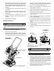
2. Apply moderate thumb pressure to belt about half way between pulleys. When properly adjusted the belt should deflect approximately 3/8” (9mm). If the belt is adjusted correctly reinstall belt guard and hardware. 3. To adjust belt tension loosen (do not remove) the (4) engine bolts. 4. Push engine towards the back of the plate. While holding pressure on the engine retighten the (4) engine bolts. spray bar on front of plate.
4. Clean all dirt and debris from exciter to prevent contamination of exciter oil. 5. Remove pipe plug from top of exciter housing. Tilt plate housing upside down to drain oil from housing. 6. 7. (Optional 3550 Only) Remove oil drain screw and brass washer from exciter rear cover. Tilt bottom plate housing on it’s side to drain oil from housing. After draining oil, return bottom plate housing to the upright position and replace oil drain screw and brass washer.
SERVICE Assembly and disassembly should be performed by a service technician who has been factory trained on MBW equipment. The unit should be clean and free of debris. Pressure washing before disassembly is recommended. Service Tools 17320 Ground Pounder® Exciter Oil • Prior to assembly, wash all parts in a suitable cleaner or solvent. 016129 Rubber Test Mat 12100 Decal Set Part No. • Check moving parts for wear and failure.
(2000) Exciter Assembly Refer to 2000 & 2018 EXCITER ASSEMBLY, page 14. for exciter disassembly. 1. 4. Support exciter assembly on outside diameter of exciter housing (1) and press exciter shaft out of housing. 5. Remove 6 flange screws (25) from front cover plate (3) and remove front cover. Prior to assembly, clean all parts in a suitable solvent or cleaning solution. When a complete disassembly is done it is recommended that all seals, gaskets and bearings are replaced.
7. Check and set end of spirol pin (23) to be 11/16” from inside of rear cover (4). See Figure 4. 17. Install new gasket (17), front cover (3) and 6 flange screws (25). Torque flange screws to 13 ft.-lbs. 8. Press bearing (11) into rear cover (4) and install snap ring (8) and gasket (18). 18. Install new gasket (18), rear cover (6) and 6 flange screws (25). Torque flange screws to 13 ft.-lbs.
REPLACEMENT PARTS The warranty is stated in this book on page 26. Failure to return the Warranty Registration Card renders the warranty null and void. MBW has established a network of reputable distributors/ dealers with trained mechanics and full facilities for maintenance and rebuilding, and to carry an adequate parts stock in all areas of the country. Their sales engineers are available for professional consultation.
This page intentionally left blank.
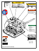
9 23 21 11 6 25 14 7 26 12 2 4 5 10 18 13 20 22 19 1 17 3 24 8 25 16 15 25 2000 & 2018 EXCITER ASSEMBLY - 14 - 23
ITEM 1. 2. 3. 4. 5. 6. 7. 8. 9. 10. 11. 12. 13. 14. 15. 16. 17. 18. 19. 20. 21. 22. 23. 24. 25. 26. PART NO. 00201 00206 00259 01004 01070 01071 01072 01099 01191 06096 06097 13451 17179 01002 18696 18697 18701 19135 01283 19628 DESCRIPTION EXCITER HOUSING REAR COVER SHIM, EXCITER (AS REQUIRED) CYLINDRICAL ROLLER BEARING BALL BEARING RETAINING RING, EXTERNAL FILTER, FELT WASHER RETAINING RING, INTERNAL GASKET GASKET WASHER, 5/8, A325, STRUCTURAL OIL SEAL OIL SEAL, SERIAL NO.
15 12 7 24 2 9 21 27 28 29 22 8 11 25 13 6 18 5 23 20 17 1 27 4 26 16 24 10 19 27 14 3550 Exciter Assembly - 16 - 22 3
ITEM 1. 2. 3. 4. 5. 6. 7. 8. 9. 10. 11. 12. 13. 14. 15. 16. 17. 18. 19. 20. 21. 22. 23. 24. 25. 26. 27. 28. 29. PART NO.
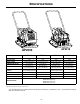
%27720 (1*,1( 5(&2,/ 6&5(: +21'$ 21/< 52%,1 (1*,1(6 21/< ENGINE ASSEMBLY 2000/2018 - 18 -
ITEM 1. 2. 3. 4. 5. 6. 7. 8. 9. 10. 11. 12. 13. 14. 15. 16. 17. 18. 19. 20. 21. 22. PART NO. 00031 00032 00048 01011 01013 01099 01444 17210 17370 20382 07636 19531 19447 16105 F0203HTB F051814HCS F0518FN F052408HCS F05LW F05SW F06SW F081305HCS F081306HCS F08LW M12ETLW M06C010BCS DESCRIPTION 2000H 2000R 2000B 2018H 2018R 2018B MOUNTING BAR, ENGINE 2 2 2 2 2 2 SHAFT KEY, 3/16” SQUARE x 1-5/8 LG.
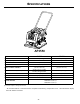
%27720 (1*,1( 5(&2,/ 6&5(: +21'$ 21/< 52%,1 (1*,1( 21/< ENGINE ASSEMBLY 3550 - 20 -
ITEM 1. 2. 3. 4. 5. 6. 7. 8. 9. 10. 11. 12. 13. 14. 15. 16. 17. 18. 19. 20. 21. 22. PART NO. 00031 00032 00048 01011 07288 06931 01099 01444 17210 17370 07636 19531 16105 F0203HTB F051814HCS F0518FN F052408HCS F05LW F05SW F06SW F081306HCS F081307HCS F08LW M12ETLW M06C010BCS DESCRIPTION MOUNTING BAR, ENGINE SHAFT KEY, 3/16” SQUARE x 1-5/8 LG.
1 22 15 20 18 9 18 11 23 2 10 23 8 21 11 23 13 4 3 21 23 17 20 22 5 13 14 23 6 12 21 23 7 23 23 17 10 15 16 19 ROLLCAGE ASSEMBLY - 22 - 21 21
ITEM 1. 2. 3. 4. 5. 6. 7. 8. 9. 10. 11. 12. 13. 14. 15. 16. 17. 18. 19. 20. 21. 22. 23. PART NO. 00226 01019 12891 13947 14202 15697 18753 15765 18690 15830 15941 16189 16191 16201 18583 16227 16365 17170 17722 18722 F051806FWS F061605FWS F0616FN F06LW F081305HCS F061606SCSSS M12ETLW DESCRIPTION HANDLE, COATED (INCLUDES ITEMS 2 & 11) HANDLE BUSHING, INNER FITTING, 90 DEG.
:$7(5 7$1. &$36 86( 7$1. &$3 86( 7$1.
ITEM 1. 2. 3. 4. 5. 6. 7. 8. 9. 10. 11. 12. 13. 14. 15. 16. 17. 18. 19. 20. 21. 22. PART NO. 00044 19495 00196 00226 01019 01026 05578 06326 08442 15765 15830 16189 16191 16227 17170 19449 19460 19454 F051806FWS F061605FWS F081305HCS F081306HCS M12ETLW DESCRIPTION PAD, RUBBER CAP, WATER TANK - FOR USE WITH 1.75” OD TANK CAP, WATER TANK - FOR USE WITH 1.
WARRANTY WHAT DOES THIS WARRANTY COVER? MBW, Incorporated (MBW) warrants each New Machine against defects in material and workmanship for a period of twelve (12) months. "New Machine" means a machine shipped directly from MBW or authorized MBW dealer to the end user. This warranty commences on the first day the machine is sold, assigned to a rental fleet, or otherwise put to first use. MBW warrants each Demonstration Machine against defects in material and workmanship for a period of six (6) months.