
Data Sheet

Be careful also before plugging the power supply into the PS (outputs or input)! Make sure the
source voltage does not exceed 32V (absolute maximum)! A lower voltage is better – we
recommend 30V or less. If you exceed 32V, you can permanently damage the product.
Also, be careful when connecting polarity wires. The polarity protection will only trip when you
connect the common (+) and V+ inputs to the same power source and load(s) (see Fig. 9).
Unfortunately, polarity protection cannot protect the device if you do not connect anything to the
V+ input. Protection will only work partially if you connect multiple voltage sources – in this case,
the polarity protection will only work for the power source that is connected to V+. If you reverse
polarities for those which are connected separately (for example, Fig. 11, closed loops through
the low-side with inverted polarities), you will have the opposite current, which will burn the
output drivers.
All nominal parameters specified in this document are determined by testing the board at room
temperature, +15…+25°C.
Input/output voltages
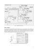
The power supply voltage is 7...30V. The absolute minimum and maximum is 6...32V. Any PS
can control very low voltages, e.g. even from 100mV. Therefore, evaluate the maximum output
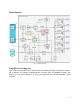
current according to the output resistance (see Fig. 7). The minimum input voltage is significant
for the Step down converter to run, which can power the 5V PS circuit and the Arduino
controller, as well as to determine the sufficient voltage for controlling the input current transistor
Q1 gate. Therefore, if you work with voltage lower than +6V, you must power the board in a
different way, i.e. from an Arduino board, USB, or Vin (according to the specific input voltage
requirements of the Arduino board). In this case, it is best to leave both V+ terminals
unconnected; otherwise, protection may be triggered and the outputs blocked.
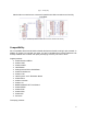
Output voltage can be different at each of the 6 channels because of the Low-Side driver’s
benefits!
Wide operational voltage range – outputs can control loads on 1...32V voltage supplies!
Current, limits and protection
● Maximum DC input current protection 25A [moderate reaction]
Response time at GND input current, i.e. sudden increase from ~1A to ~45A (or more) is ~250 ms.
● Maximum input pulse current protection ~280A [quick reaction]
Response time ~2ms. Warning: peak output power can reach 8kW!
● Thermal direct current protection per channel 6...8A [slow reaction]
The higher the temperature of a specific output driver, the faster the reaction. 1...100s.
● Current limitation via channel (when warning indicator is off) ~40A [quick reaction]
Response time about ~1ms.
● Current limitation for the channel (when warning indicator is on) ~15 A [quick reaction]
Response time about ~1ms.
8