
Data Sheet

Demo programs for Arduino
Download and test sketches
You can download two programs (sketches) and upload them to your Arduino microcontroller.
One of them is simplified program for beginners and other one is for more advanced or
professional users.
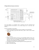
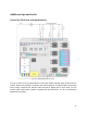
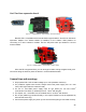
Once you have uploaded one of these programs and connected the Arduino to the PS board(s),
connect something to the outputs to test them. For testing, we recommend connecting the bulbs
as shown in Fig. 24 (Stack PS to multiply outputs to 12) or 6 simple LED strips. On one board,
switch SW1 to ON and on the other board switch SW1 to OFF.
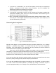
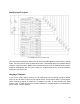
This sketch controls all main outputs from 2 to 13. Duty cycle signals are output on PWM
outputs (3, 5, 6, 9, 10, 11), while the switching signals are output on the remaining outputs (2, 4,
7, 8, 12, 13).
Therefore, if you are using only one board, switch SW1 depending on which outputs you want –
PWMs or simple. For example, on Arduino MEGA, all outputs D2...D12 are PWM. Therefore,
you can program the outputs so that PWM operates even when SW1 is off.
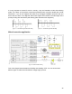
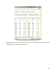
Analog inputs (A0...A5) are used here for FeedBack reception from PS.
If SW2 is ON, the shield returns three types of FeedBacks:
● A0 or A2 – Error; all outputs disabled for a few seconds (red blinking LED)
● A1 or A4 – Warning
(yellow LED)
● A2 or A5 – Analogue output voltage of 1V equivalent to 10A (20A for stacked version
when both SW1 switches set into same possition) of input current (blue LED)
All of these inputs can be monitored by turning on the Serial Monitor (with a baud rate of
19200). The return of FeedBack signals (to A0, A1, A2 or A3, A4, A5) will depend on the
position of the SW1 switch (outputs to analogue inputs).
25