
Data Sheet
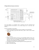
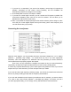
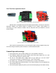

It is very important to choose R1 and C1 correctly – they are intended to reduce the switching
peaks. The values of the passive components presented here have been tested with a ferrite
transformer. If you do not suppress the peaks, they will trigger FlashBack protection and your
device will shut down. The diagrams below show signal forms between the side edges of the
primary winding with and without peak filtering (with and without RC suppresor):
[Fig 21.1 – Transformer signal without RC filter] [Fig 21.2 – Transformer signal with RC filter]
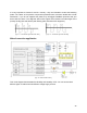
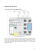
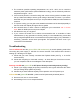
Mixed connection application
[Fig. 22 –Various loads connect]
This circuit diagram demonstrates the flexibility and versatility of PS. You can connect both
different types of loads as well as different voltage supply sources.
22