
Data Sheet
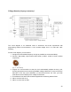
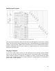
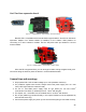

7. If you use C1 or especially if you use the C2 capacitor, use as large of a capacity as
possible. Increasing C2 will reduce current instability, and the FeedBack will
automatically measure the voltage more accurately.
8. D1 Schottky diode could be, for example, 1N5822.
9. If you want to control higher currents, you can connect the PS outputs in parallel. We
recommend separating them with the R3 and R4 resistors. This will allow you to
distribute the output current more evenly.
10. Also, if you parallel the outputs (through the R3 and R4 resistors), before doing so, make
sure that your chosen digital outputs work synchronously (at the same frequency and
coincide with the duty cycle phase).
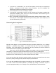
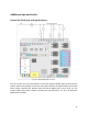
Connecting the transformer
[Fig. 20 –Transformer with centre-tap application]
With this circuit diagram, you can generate almost any secondary voltage from ~1V to ~5000V
(attention – potentially high voltage – be careful and only use if you have appropriate
education). This circuit diagram is for advanced users only because you need to select the
correct transformer and properly program the outputs.
First of all, it is very important to configure the outputs so they can open alternatively:
respectively, D5 with D6 for upper and D9 with D10 for lower, primary winding poles.
It is also very important that the duty cycle of each signal is not greater than 48% if you work at
frequencies up to 1kHz and 42% if you work at frequencies up to 10kHz.
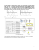
If you want to build a high frequency switching supply, use a ferrite core transformer with about
20 turns in primary winding (2x10W). Set the frequency at about 8kHz.
If you work with a 50/60Hz (mains frequency) transformer and, for example, you want to make a
110...120V or 220...240V inverter (attention – potentially high voltage – be careful, only use if
you have appropriate skills), you can simply use any standard electric steel transformer.
21