
Data Sheet
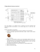
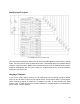
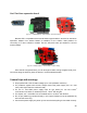

Voltage booster (step-up converter)
[Fig. 18 – Step up converter – voltage multiplier]
The circuit diagram is for advanced users of electronics and those experienced with
programming Arduino microcontrollers. It can increase voltage from 7V to 28V with ~90%
efficiency.
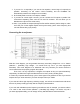
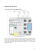
For this circuit diagram, you will need to:
1. Configure the board PWM frequency as high as possible (we recommend 8kHz)
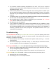
2. Choose a high-quality, high-current toroid inductor (~470µH...2.2mH & <0.3Ω or similar
component)
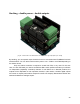
[Fig. 19 – Toroid inductor]
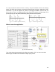
3. Program the microcontroller so that the circuit automatically adjusts the duty cycle,
inversely proportional to the returning FeedBack voltage. Make sure to never reach more
than 80% of the duty cycle! Otherwise, you will short-circuit the coil. Also, your code
must disconnect the output(s) if the voltage exceeds 28V.
4. The feedback in the best case should be supplied to the following Arduino PINs:
5. *A3 or A4 when SW1 is up
6. *A0 or A1 when SW1 is down
20