
Data Sheet

This way you can power a variety of objects, for example Peltier elements, heating elements, or
hydrogen trays, or even charge any battery. Also, the circuit will work more efficiently.
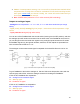
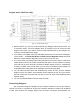
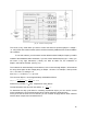
Driving 100W 35V LEDs easily
[Fig. 17 – 100W LED]
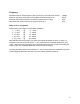
Here is an example of how you can exclusively control 31–33V 100W LEDs with a 36V power
supply. Since the voltage used exceeds the rated voltage of the PS, the following requirements
must be met:
● Use resistor R1 with minimum parasitic inductance.
● Important: do not power the board with a 36V (BT1) power supply! It is used only for the
LED circuit(s) described here.
● Use a separate power supply for powering the board logic (see Low voltage).
● For long-term use, calculate R1 according to the specific LED specifications and power
supply. For example, in our case, a voltage of 4 V dropped across the resistor and we
selected a resistance of 1.5Ω. This way we limited the maximum current to 2.7A.
● Be careful with frequency increases (overcharging). Above 2kHz, the operation of the
device may be influenced by parasitic inductance. For heavy loads, we recommend
using only the default frequency.
● Only 30...35V LEDs are suitable for this circuit diagram. For other cases, over-voltage
cannot be used at this point! The 30V LED is an exception because the difference in
power voltage drop on it is taken off from the BT1; therefore, this voltage in this case will
not damage the PS outputs.
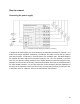
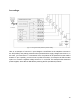
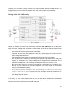
In this way, you can control (adjust power or turn ON and OFF) 6 independent 100W LEDs
using all channels. In total, you will have up to 600W LED power, or you can connect LEDs in
sequence and use the same power across all channels.
19