
Data Sheet
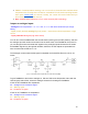
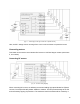
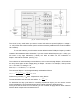

[Fig. 16 – Inductor for driving LEDs]
The circuit is very useful when you want to control 1W and more powerful (Object 1 voltage =
~2...25V) LEDs with minimal losses (which could be caused by traditional LED current limitation
via a resistor).
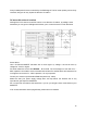
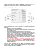
To use this method, you will need to set the default Arduino PWM pin frequency to 8kHz
instead of the standard 0.5kHz. Otherwise, if you use a lower default frequency (0.5...1kHz), you
will need a very high inductance (~15mH) coil. With an 8kHz coil, the inductance of
500μH...2mH will be sufficient (see Fig. 19).
The inductive coil works similarly to a transformer, so the current through Object 1 will be almost
as many times higher as the voltage (drop) on Object 1 is lower. For example, if the input has
U
BT1
= 15V and I
output
average = 1A,
then U
Object
1 = 5V and I
Object
1 = up to 3A.
The current of Object 1 can be approximately calculated as follows:
Ƞ 0.9 .7AI
Object 1
=
U
Objec1
U ⋅ I
BT 1 output average
=
5V
15V ⋅1A
= 2
Quiescent Ƞ is usually 90%. It depends on many factors.
The transformation ratio K in this case will be: K =
U
BT 1
U
Objec1
= 3
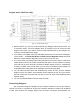
To determine the duty cycle limits for controlling a particular object, you can use the current
meter integrated for current measurement (which outputs a signal to analogue pins).
Once you’ve set the limits for one channel, you can continue to apply them to other channels
with the same components connected to them.
18