
Data Sheet
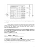

Stepper motor (UniPolar only)
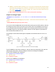
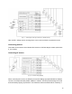
[Fig. 14 – UniPolar stepper motor]
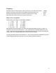
● With this device, you can only control UniPolar type Stepper motors (which have 5, 6 or
8 connection wires). The circuit diagram gives an example of how to connect a 6-wire
stepper motor. Note: If you want to control a motor rated less than 7V (for example, 5V),
connect it to a separate power supply.
● If you want a more stable motor step and better performance, we recommend installing a
current limiter – the Buck Step Down Constant Current Regulator series work best.
Select the current limitation depending on the motor (from 0.1A to 5A).
● The current limiter will greatly improve the performance of the motor when it needs to be
rotated slowly and acts as a brake mechanism (with direct current), thanks to which the
motor will heat up much less! We recommend 1000μF capacity for the C1. Alternatively,
for testing, instead of the current limiter you can use an incandescent lamp (halogen) or
a separate power supply that has an integrated current limiting capability.
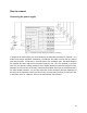
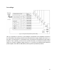
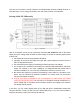
● You can stack two PS boards and simultaneously control as many as three UniPolar
stepper motors; one Arduino microcontroller will be sufficient for this. And if you want to
limit the current here, be aware that you have to limit it for each motor separately with a
separate limiter.
● You can use UF4004 diodes from this series or similar.
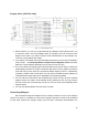
Connecting halogens
We recommend using 24V halogens for up to 70W per channel or 12V for up to 35W per
channel. Of course, it is possible to connect more powerful elements, but then it will be difficult
to start them because the halogen lamps have non-linear volt-ampere characteristics: the
16