
Data Sheet

● Yellow – Overtemperature warning
; one or more of the 6 channels have reached critical
temperature due to being short-circuited or overloaded. PS will continue working but with
lower peak current limits per channel. Usually, the current will remain limited until you
shut off the power or pull the reset pin.
● Red – ERROR when protection is on for a few seconds (PS is rebooting)
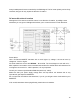
Outputs to analogue inputs
- Analogue current expression – 1V <==> 10A; 1V <==> 20A when stacked at input merge
setting
- Digital (usually latched) warning
(High out) output – warns about critical temperature or high
current
- Digital protection on signal (high when active)
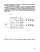
You can turn off the FeedBack with the second switch (lowering it to the OFF position), and then
the analogue pins will remain unconnected. On the other hand, if the FeedBacks are turned on,
you can still ignore them and send their signals to any analogue inputs because the PS sends
all FeedBack signals only through 22k resistors; therefore, the PS outputs are protected from
short circuits to either GND or to + 5V.
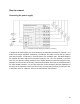
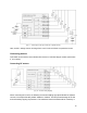
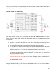
The analogue current measurement signal is outputted via the dual RC filter to the A5 or A2
inputs:
[Fig. 8 – PS internal circuit: output filter for current sense amplifier]
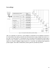
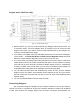
To get FeedBacks to the Arduino analogue in, first turn SW2 to the ON position. Next, with the
channel group switch SW1, select the analogue channels for feeding the FeedBacks.
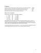
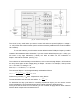
If SW1 is ON, FeedBacks are outputted to:
A5 – Analogue current measure signal
A4 – Warning signal
A3 – Protection on signal
If SW1 is off, FeedBacks are outputted to:
A2 – Analogue current measure signal
A1 – Warning signal
A0 – Protection on signal
10