
Data Sheet


Impedance
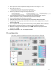
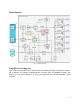
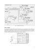
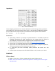
[Fig. 7 – Power circuit impedance]
These imaginary impedances R0…R6 were deducted from the following operating conditions:
input voltage 24V, current 23A (100% of duty cycle). In other words, the voltage drop between
the input GND and the output terminals was measured and the impedance was calculated:
R
0
= ~3.61mΩ, R
1
….R
6
= ~56.7mΩ.
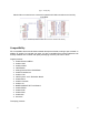
Protection
● Input polarity protection. By reversing the potential between V+ and GND, the protection
completely disconnects the GND, including from the outputs (since the device is
Low-Side type). This ensures that no negative current is supplied to the outputs.
● Fifth-level current protection (for more details, see Current, limits and protection).
● Logic circuits 5V overvoltage protection with 5V6 TVS.
● Logic circuits overcurrent protection with 0.5A PPTC at +85°C (at higher temperatures,
overcurrent protection may be activated at a lower current).
● V+ input ESD (and short overvoltage peaks) protection with bipolar 33V TVS
component.
● All signal inputs and outputs have ESD HBM JESD22-A114F protection up to 2000V.
FeedBacks
LEDs on board
● Green – Power okay; +5V logic voltage supply is present (higher than 4V)
● Blue – Overcurrent indicator; flashes when (pulsed or constant) input current is higher
than about 20A
9