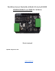
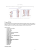
Multifunctional, Stackable & Multi-Protected 800W POWER SHIELD 6+6 T800 for Arduino [Fig. 1 – POWER SHIELD 6+6 T800, top view] User manual Updated: August 29, 2018 www.v-vTech.
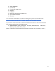
Table of Contents Table of Contents Product overview Electrical safety Main features Pin configuration Compatibility Block diagram Simplified circuit diagram Power supply Input/output voltages Current, limits and protection Impedance Protection FeedBacks LEDs on board Outputs to analogue inputs Frequency Duty cycle vs.
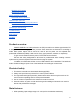
Multiplying PS outputs Merging PS outputs Demo programs for Arduino Download and test sketches Additional tips and tricks Control the PS directly with push buttons Use PS as Nano expansion board General tips and warnings Troubleshooting Best wishes! Contacts Product overview POWER SHIELD 6+6 T800 (referred to as PS) is an add-on to Arduino-type boards. PS is designed to handle strong (up to 25A) currents. Each board has 6 channels for controlling 6 loads.
2. Each output can control independent voltage sources in the range of 1...32V. 3. High output frequencies: ● ● Without heat sinks: at full load 0…2kHz, fully covering Arduino board’s default PWM speed. With additional heat sinks on transistors: 4…25kHz at full power. 25…100kHz with smaller currents. 4.
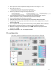
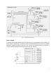
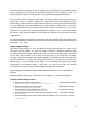
[Fig. 2 – PS top plan] Arduino Nano connections are connected in parallel with UNO connections and are fully compatible: [Fig. 3 – Relationship between Arduino UNO and Arduino NANO shield headers] Compatibility PS is compatible with almost all Arduino-based development boards, making it quite versatile. In addition to working for intended use cases it is also compatible with processor platforms both already available on the market and rapidly developing.
● ● ● ● ● ● ● ● Infinion XMC4700 ST NUCLEO ST NUCLEO (NANO size) KeyDuino FireBird32 RaspDuino (transition to Raspberry Pi) Cytron ARM Cortex M0 And more You can see the extended list of products including many other microcontrollers here: https://en.wikipedia.
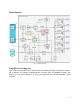
Block diagram [Fig. 4 – Internal structure] Simplified circuit diagram This circuit is only symbolic and is used to show the operating principle. In reality, the circuit on PS is different. The majority of safeguards are not shown here; no FeedBack is shown. The purpose of this circuit diagram is to help you understand the Low-Side transistor control principle.
[Fig. 5 – Simplified internal structure] Power supply The board has a DC/DC (BUCK step-down high efficiency) converter that provides a stable +5V power supply to the PS logic circuits and powers the attached Arduino board and other possible expansion modules connected to the top. The converter (for external devices) can deliver a current of 450mA, though we recommend to use only up to 300mA. [Fig.
Be careful also before plugging the power supply into the PS (outputs or input)! Make sure the source voltage does not exceed 32V (absolute maximum)! A lower voltage is better – we recommend 30V or less. If you exceed 32V, you can permanently damage the product. Also, be careful when connecting polarity wires. The polarity protection will only trip when you connect the common (+) and V+ inputs to the same power source and load(s) (see Fig. 9).
Impedance [Fig. 7 – Power circuit impedance] These imaginary impedances R0…R6 were deducted from the following operating conditions: input voltage 24V, current 23A (100% of duty cycle). In other words, the voltage drop between the input GND and the output terminals was measured and the impedance was calculated: R0 = ~3.61mΩ, R1….R6 = ~56.7mΩ. Protection ● ● ● ● ● ● Input polarity protection.
● ● Yellow – Overtemperature warning; one or more of the 6 channels have reached critical temperature due to being short-circuited or overloaded. PS will continue working but with lower peak current limits per channel. Usually, the current will remain limited until you shut off the power or pull the reset pin.
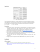
Frequency Absolute maximum output frequency with current up to 0.5A output per channel Maximum frequency at full power using additional heat sinks and/or fan Maximum safe output frequency at full power (without active cooling) Recommended output frequency for long-term work up to - 100kHz - 25kHz - 4kHz - 2kHz Duty cycle vs. frequency Possible duty cycle ranges for pulse-width modulation: ● 1...98% @ 0…..2kHz ● 6...90% @ 2…10kHz ● 10...80% @ 10…20kHz ● 25...55% @ 20…50kHz ● only ~45% @ 50..
How to connect Connecting the power supply [Fig. 9 – The simplest connection diagram for utilisation of all channels] In parallel to the power supply, we recommend that you install the electrolytic C1 capacitor – it is better to use larger capacities, respectively, according to the loads. Let’s say that you want to work with full power. In that case, it would be best to use 10'000μF / 50V. The rated voltage of the capacitor should be higher than the power supply by +20….30%.
Low voltage [Fig. 10 – PS logical circuits powered by Arduino USB] Here is an example of how the V+ input voltage is not sufficient for the stepdown converter in the PS (DC/DC) and polarity protection when powered with a supply voltage lower than 6V; in this case, you must leave V+ unconnected. Here, the product will be powered from the Arduino board’s 5V pin. Hopefully you know how to power the Arduino, for example via USB. Another option is to connect a separate voltage source to V+ on the PS.
[Fig. 11 – Power supply of the logic circuits from a separate source] Here, the BT1 voltage source can range from 0.01V to 32V as it does not power the board. Connecting motors This board can be used to control brushed DC motors or UniPolar Stepper motors (which have 5, 6 or 8 wires). Connecting DC motors [Fig. 12 – DC motor wiring diagram] When connecting DC motors, we definitely recommend adding high-speed diodes for FlyBack currents, for example Schottky diodes 1N5822 or 1N5819.
heavy loaded powerful motor controlled by the PWM signal. The DC motor polarity can be freely reversed; doing so will only impact the direction of rotation. DC motor direction of rotation Although the PS is used to control DC motors in one direction of rotation, by adding 2 extra transistors you can get an H-Bridge which allows you to control the motor in both directions. [Fig. 13 – H-Bridge] Some advice: Use a P-Channel MOSFET transistor with a much higher Ugs voltage.
Stepper motor (UniPolar only) [Fig. 14 – UniPolar stepper motor] ● ● ● ● ● With this device, you can only control UniPolar type Stepper motors (which have 5, 6 or 8 connection wires). The circuit diagram gives an example of how to connect a 6-wire stepper motor. Note: If you want to control a motor rated less than 7V (for example, 5V), connect it to a separate power supply.
resistance of the cold filament is ~14 times less than that of the illuminating, and therefore the start current is automatically ~14 times higher. Using halogen lamps with the lowest duty cycles and at the highest frequencies (more than 2kHz) can generate (due to inductance) narrow but very strong back current peaks that can trigger the FlashBack detector and activate the protection, which means switching off the outputs.
[Fig. 16 – Inductor for driving LEDs] The circuit is very useful when you want to control 1W and more powerful (Object 1 voltage = ~2...25V) LEDs with minimal losses (which could be caused by traditional LED current limitation via a resistor). To use this method, you will need to set the default Arduino PWM pin frequency to 8kHz instead of the standard 0.5kHz. Otherwise, if you use a lower default frequency (0.5...1kHz), you will need a very high inductance (~15mH) coil.
This way you can power a variety of objects, for example Peltier elements, heating elements, or hydrogen trays, or even charge any battery. Also, the circuit will work more efficiently. Driving 100W 35V LEDs easily [Fig. 17 – 100W LED] Here is an example of how you can exclusively control 31–33V 100W LEDs with a 36V power supply. Since the voltage used exceeds the rated voltage of the PS, the following requirements must be met: ● Use resistor R1 with minimum parasitic inductance.
Voltage booster (step-up converter) [Fig. 18 – Step up converter – voltage multiplier] The circuit diagram is for advanced users of electronics and those experienced with programming Arduino microcontrollers. It can increase voltage from 7V to 28V with ~90% efficiency. For this circuit diagram, you will need to: 1. Configure the board PWM frequency as high as possible (we recommend 8kHz) 2. Choose a high-quality, high-current toroid inductor (~470µH...2.2mH & <0.3Ω or similar component) [Fig.
7. If you use C1 or especially if you use the C2 capacitor, use as large of a capacity as possible. Increasing C2 will reduce current instability, and the FeedBack will automatically measure the voltage more accurately. 8. D1 Schottky diode could be, for example, 1N5822. 9. If you want to control higher currents, you can connect the PS outputs in parallel. We recommend separating them with the R3 and R4 resistors. This will allow you to distribute the output current more evenly. 10.
It is very important to choose R1 and C1 correctly – they are intended to reduce the switching peaks. The values of the passive components presented here have been tested with a ferrite transformer. If you do not suppress the peaks, they will trigger FlashBack protection and your device will shut down. The diagrams below show signal forms between the side edges of the primary winding with and without peak filtering (with and without RC suppresor): [Fig 21.1 – Transformer signal without RC filter] [Fig 21.
Stacking – double power – double outputs [Fig. 23 – Arduino UNO + two stacked PSs to use 12 channels to get output power up to 1.5kW] By stacking, you can expand output channels from 6 to 12 and also have FeedBacks from both stacked boards. You can select which Arduino ports to use – PWM or non-PWM depending on the Arduino board. Only one Arduino controller is required to control both PSs, in any case.
Multiplying PS outputs [Fig. 24 – Example of two stacked PSs] We recommend installing the board that will work with PWM signals on top because it will get hotter. This way it will be easier to dissipate the heat. If both boards will work in PWM mode (for example, using the Arduino MEGA microcontroller because it has 15 PWM channels) with the maximum load applied, then use active cooling (i.e. a high-flow server fan). The best ventilation direction is from right to left.
Demo programs for Arduino Download and test sketches You can download two programs (sketches) and upload them to your Arduino microcontroller. One of them is simplified program for beginners and other one is for more advanced or professional users. Once you have uploaded one of these programs and connected the Arduino to the PS board(s), connect something to the outputs to test them. For testing, we recommend connecting the bulbs as shown in Fig.
[Fig. 25 – FeedBack outputs to Arduino serial monitor form one PS] In the case of stacking, when the SW1 of one board is ON and the other is OFF, this window will display the parameters on the left and right. All 6 FeedBacks will run simultaneously, and 2 ammeters will work.
Additional tips and tricks Control the PS directly with push buttons [Fig. 25 – Control outputs with push buttons] You can connect up to six push buttons to control the outputs manually (they will be turned on until the buttons are pressed). In this case, the Arduino board is no longer needed. On the other hand, having connected the Arduino board and set its digital pins to input mode, you can monitor button clicks. When a button is pressed, the input will have 4...5V.
Use PS as Nano expansion board [Fig. 26.1 – POWER SHIELD + Arduino NANO + some other shield] Because PS is compatible with almost all Arduino-type boards, it can also be used as an expansion adapter from Arduino NANO (or MICRO*) to the Arduino UNO platform for connecting it to other extension modules. Use the low-profile male pin headers to connect Arduino NANO. [Fig. 26.
● ● ● ● ● ● The maximum possible operating temperatures are -20°C...+50°C, but to reach the maximum power performance (without additional cooling), use the board only within the temperature range 0...+30°C. If the board is placed in a closed housing, take care to ensure good air circulation (from the top, bottom and sides) to ensure good cooling of the board. Of course, if you use the board with only low load (total current up to 15A) and without PWM, the board should not overheat.
No signs of operation, no LED is ON: A. You have reversed the polarity B. No voltage, or voltage from power supply is too low You activated the outputs and then the blue LED blinked while the yellow warning LED went ON along with it: A. The load connected is probably too high or the output has short-circuited. Yellow warning LED is on – you can reset this status in three ways: A. By pushing the reset button on the Arduino B. By supplying very low (0.0V) digital signal to any of the reset pins C.