Quick Start Installation Guide Nautic NSB6V1 / NSB10V1 Soundbars
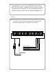
Congratulations on your choice of MB Quart Nautic Sound Bars.This “Quick Start” Installation guide is meant to help you complete a basic installation. For more detailed information about the product, please visit our website at MBQuart.com Wiring The wiring and connections should be secure and away from any moving parts or extremely hot surfaces. Red - 12v Power Orange - Ignition Switch Input Black - Ground Blue - Remote Out 3.
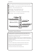
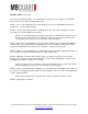
Controls 1 Power - Will turn the unit on or off / Five second hold/ quick push will switch inputs. 2 Track BACKWARDS - Press to restart the current track or to back up to previous tracks. 3 Volume UP - Each press will increase the volume. 4 Volume DOWN - Each press will decrease the volume. 5 Track FORWARD - Press to advance to the next track. 6 Map Light / Illumination - Turn on Map Light, cycle through illumination settings. 7 PLAY / PAUSE - Press once to pause. Press again to play.
WARRANTY Maxxsonics USA Inc. warrants this product, to the original consumer purchaser, to be free from defects in material and workmanship for a period of one (1) year from the date of purchase. Maxxsonics USA Inc. will, at it’s discretion, repair or replace defective products during the warranty period. Components that prove to be defective in materials and workmanship under proper installation and use must be returned to the original authorized Maxxsonics USA Inc. retailer from where it was purchased.
SOUND BAR MOUNTING The following is intended to help you mount the sound bar. We highly recommend employing the expertise of a professional installer. The sound bar has two convenient installation styles. Roll Cage and Surface Mount review this document to determine which you will use, then prepare for installation. A. Prepare a flat work surface to prepare for installation B. Recruit an assistant to help with lifting Sound Bar into place C.
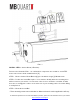
FIG 1-1 INSTALL STEPS - Surface Mount (L Brackets) Reference the illustration FIG 1-1 to confirm which components are needed for each STEP. Items on the list are called out with brackets [X]. STEP 1 - Mount 1 Surface Mount Bracket [6] per side with the longer [7] M5x20 screws. STEP 2 - Position the Sound Bar in place. Use a marker to identify where the mounting holes will be located on your vehicle. Use at least 2 of the 3 holes to mount the sound bar.
INSTALL STEPS - Roll Cage Reference the illustration FIG 1-1 to confirm which components are needed for each STEP. Items on the list are called out with brackets [X]. STEP 1 - Choose the appropriate Top Tube Clamp [1] for your roll cage diameter. We have included 1.5, 1.75 and 2 inch clamps. STEP 2 - Insert 2 slide lugs [2] into the mounting channel on top of the sound bar. You want these lugs to be left and right in the channel.
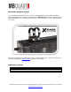
ADDITIONAL MOUNTING OPTIONS If you find that your installation is more exotic or challenging that can be addressed with the included hardware we recommend our build partner AXIA ALLOYS. They offer a wide variety of billet aluminum mounts mounting system for more accessories that you can possibly install on your vehicle. Here is a link for with the components for your sound bar. Make sure to check out all the other mounting creativity from AXIA ALLOYS while you’re on the site.