
Specifications

©2004 Maytag Services 16023430 Rev. 0 13
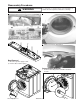
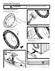
Troubleshooting Procedures
!
WARNING
To avoid risk of electrical shock, personal injury or death, disconnect power to unit before servicing, unless testing
requires power.
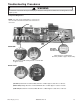
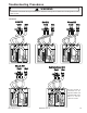
Component Diagnostics
NOTE: For ohm checks unplug harness connector on
console and test from wire insertion side of the harness
connectors.
Blue wire Pin 2 on CN6 to Gray wire Pin 1 on CN3 120V
or approx 16 ohms
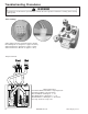
( ) Red wire Pin 4 on CN3 to White wi
Hot Valve
re Pin 1 on Main. Approx 11,000 ohms or 120 volts.
( ) Orange wire Pin 3 on CN3 to White
Bleach Valve
wire Pin 1 on Main. Approx 11,000 or 120 volts.
( ) Blue wire Pin 2 on CN3 to White wi
Cold Valve
re Pin 1 on Main. Approx 11,000 ohms or 120 volts.
4 3 2 1
12
5 4 3 2 1
Yellow wire Pin 3 on CN4 to Pink
wire Pin 4 (5V+DC or approx 12,000 ohms)
4 3 2 1
8
CN3
MAIN
Tub Sump
Thermistor/
2
1
DRAIN PUMP
WATER VALVE
CN3
CN4
Pressure SW
Main