Service This manual is to be used by qualified appliance technicians only. Maytag does not assume any responsibility for property damage or personal injury for improper service procedures done by an unqualified person.
Important Information Important Notices for Technicians and Consumers Maytag will not be responsible for personal injury or property damage from improper service procedures. Pride and workmanship go into every product to provide our customers with quality products. It is possible, however, that during its lifetime a product may require service.
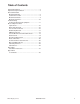
Table of Contents Important Information .................................................... 2 Important Safety Information ......................................... 4 General Information Model Identification .................................................... 8 Serial Label Location ................................................. 8 Model Nomenclature .................................................. 9 Model Specifications .................................................
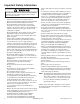
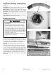
Important Safety Information To reduce the risk of fire, electric shock, serious injury or death to persons when using your washer, follow these basic precautions: • Read all instructions before using the washer. • Refer to the Grounding Instructions in the Installation Manual for the proper grounding of the washer.
Important Safety Information To avoid personal injury or death from improper servicing, make sure you read and understand the descriptions and meaning of various safety symbols, words and labels used in this manual, before attempting any procedures described in the manual. Failure to understand and comply with safety information may result in severe personal injury or death. General Information This Service Manual describes the operation, disassembly, troubleshooting, and repair of the Compact washer.
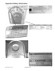
Important Safety Information Explanation Polarization–This means that the larger slot must be neutral and the small slot must be at line voltage. Mispolarized–The outlet is incorrectly wired so that the larger slot is at line voltage and the smaller slot is neutral. Grounded–This means the round hole connection is connected to earth ground through a connection to the main power panel. Ungrounded–The round hole connection is not complete to earth ground and/or the main power panel.
Important Safety Information ©2004 Maytag Services 16023430 Rev.
General Information Service Model Identification Complete registration card and promptly return. If registration card is missing: • For Maytag product call 1-800-688-9900 or visit the Web Site at www.maytag.com • For product in Canada call 1-866-587-2002 or visit the Web Site at www.maytag.com. When contacting provide product information located on rating label.
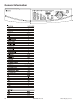
General Information Compact Washer Nomenclature M A H 2 4 0 0 A Y W Color Brand W Q M= Maytag Product Type Listing W Y Z Y AH= Automatic Horizontal 120V-60hz 240V-60hz Canada 240V-60hz 220-240 V / 50-60 Hz Marketing Code Feature Content 2400 White Bisque This identifies which version of production the unit is. Feature Package Trouble Shooting and Diagnostic Guide is Located Behind Toe Panel. ©2004 Maytag Services 16023430 Rev.
General Information 10 16023430 Rev.
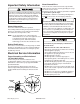
Troubleshooting Procedures ! WARNING To avoid risk of electrical shock, personal injury or death, disconnect power to unit before servicing, unless testing requires power. Place washer into Service Mode and check for diagnostic codes. See Technical Data Sheet behind Toe Panel. Will Not Start • Plug cord into live electrical outlet. Check for proper voltage. • Check fuse or reset circuit breaker. • Push the START/PAUSE button to start the clothes washer.
Troubleshooting Procedures ! WARNING To avoid risk of electrical shock, personal injury or death, disconnect power to unit before servicing, unless testing requires power. • • Manual packed behind Toe Panel. Perform Board Output Test. Check door lock system. See Technical Sheet or Mini Manual packed behind Toe Panel. Check electrical connections at lock switch assembly and Machine Control Board (CN2).
Troubleshooting Procedures ! WARNING To avoid risk of electrical shock, personal injury or death, disconnect power to unit before servicing, unless testing requires power. Component Diagnostics NOTE: For ohm checks unplug harness connector on console and test from wire insertion side of the harness connectors.
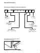
Troubleshooting Procedures ! WARNING To avoid risk of electrical shock, personal injury or death, disconnect power to unit before servicing, unless testing requires power. Motor windings 6 5 3 2 4 1 CN1 (CN1) Unplug connector and test Resistance at plug. Rotor Orange Pin 1 to Gray Pin 3 = approx 2.
>> >> > >> >> > > > >> >> > >> >>>>>>>>> >> < << >>>>>>>> >>> << << >> > > > > > > >> > > > > >>>>>>>>>> >>> > < >>>> >>> >>> << >> << << >> >>> >>> >>>>>>>> > >>>>>>> >> >> >> >> >> >> >> > >> > >>>>>>>>>>>>>>>> > > < << << << >>>>>> >> >> >> >> >>>>>>>>> > >>>>>>>>>>>> >> >> >> > >> >> >> > > > > > >> >> > >> > > > >> >>>> >> > > >> > >> > >> > > > > > > > > > > > > > > > >> > > > > > >> > >> > > > >> >>>>>>>>>>> >>>>>>>>>>>> > > The two streams of cold wate
Disassembly Procedures ! WARNING Top Removal To avoid risk of electrical shock, personal injury or death; disconnect power to unit before servicing. 4. Remove connectors. 1. Disconnect power supply to unit. 2. Remove 2 screws from washer back. 3. Slide Top Cover to the rear of the washer and separate from cabinet. 5. Remove screws retaining Water Valves. Pressure Valve Removal Water Valve Removal 1. Disconnect power supply to unit. 2. Remove Top Cover. 3. Remove hoses. 16 1. 2. 3. 4.
Disassembly Procedures ! To avoid risk of electrical shock, personal injury or death; disconnect power to unit before servicing. WARNING Drain Pump Removal 1. Disconnect power supply to unit. 2. Gain access to bottom of unit. 3. Remove 4 screws securing panel to the bottom of the cabinet. 6. Remove 4 screws and slide pump mounting bracket to free tabs and remove motor. . 4. Remove drain hose and tub hose from pump. 5. Disconnect electrical connector . ©2004 Maytag Services 16023430 Rev.
Disassembly Procedures ! To avoid risk of electrical shock, personal injury or death; disconnect power to unit before servicing. WARNING EMI Filter Removal 1. Disconnect power supply to unit. 2. Remove Top Cover. 3. Remove wiring connectors and ground wires. 4. Tip Console to access connectors. NOTE: Clip wire ties if necessary to gain access to Control Board. Console/Machine Control Board Removal 1. Disconnect power supply to unit. 2. Remove Dispenser drawer. 3.
Disassembly Procedures ! To avoid risk of electrical shock, personal injury or death; disconnect power to unit before servicing. WARNING 6. Remove 5 screws retaining Control Board to Console. 3. Remove boot retainer wire from groove. 8. Separate the Control Board from the Console. 4. Pull boot over lip on Front Panel. Boot Removal 1. Disconnect power supply to unit. 2. Remove Boot retainer spring. Door Assembly Removal 1. Remove Door Hinge with screwdriver and 5/16” wrench.
Disassembly Procedures ! WARNING Disassemble Door Assembly To avoid risk of electrical shock, personal injury or death; disconnect power to unit before servicing. 6. Remove glass sight window from frame. 1. Disconnect power supply to unit. 2. Remove Door Assembly 3. Remove screws on door inner panel. NOTE: Align indent in glass with drain hole in frame during reassembly. 4. Remove pin through door strike. Front Panel/ Door Latch Removal 1. Disconnect power supply to unit. 2. Remove Console. 3.
Disassembly Procedures ! To avoid risk of electrical shock, personal injury or death; disconnect power to unit before servicing. WARNING 5. Remove 6 screws on Front Panel top and bottom. 8. Remove 2 screws retaining Door Latch to Front Panel. Motor and Belt Removal 1. Disconnect power supply to unit. 2. Remove 3 screws retaining Back Cover. 6. Lift front Panel from hanger hooks. 3. Remove belt by pulling belt while rotating pulley causing belt to derail from motor. 7.
Disassembly Procedures ! To avoid risk of electrical shock, personal injury or death; disconnect power to unit before servicing. WARNING 5. Remove Motor wiring connector and ground wires. 6. Remove 2 1/2” Motor mounting bolts. Bolt torque is 10.8-18.1 ft. lbs. 4. Insert a 3/8” drive extension into hole in bearing cover to lock pulley from rotating. 5. Loosen bolt retaining pulley. Bolt torque is 21.7-28.9 ft. lbs. Tub Removal 7. Swing Motor down and to the left to remove. 1. 2. 3. 4. 5. 6. 7.
Disassembly Procedures ! To avoid risk of electrical shock, personal injury or death; disconnect power to unit before servicing. WARNING 9. Remove Fill Hose and Dispenser Hose from Tub. 12. Remove Dispenser from washer. 13. Remove 1/2” bolts retaining upper counter weight. Bolt torque is 10.8 to 18.1 ft. lbs. 14. Remove Upper Counter Weight. 10.Remove Dispenser Feeder Hoses. 15. Disconnect Sump Thermistor wire harness. 11. Remove screw retaining Dispenser. 16.
Disassembly Procedures ! To avoid risk of electrical shock, personal injury or death; disconnect power to unit before servicing. WARNING 17.Remove Lower Counter Weight. 20.Move Struts to center of washer. 21.Mark location and position of Suspension Springs. 18.Remove remaining wire harnesses and hose from tub. 19.Remove 2 1/2” bolts retaining the Struts. All Strut bolts are torqued to 18.1-25.3 ft. lbs. 24 22.Reinstall Upper Counter Weight bolts to tub without weight in place.
Disassembly Procedures ! To avoid risk of electrical shock, personal injury or death; disconnect power to unit before servicing. WARNING 23.Use weight bolts to lift tub and unhook Suspension Springs. 26. Remove rear Spinner Pulley. NOTE: After Spinner Pulley bolt is removed Spinner can fall from tub. Block Spinner to prevent Spinner from falling free. 27. Remove bolts around perimeter and separate the tub halves. 24.Grasp the front and rear of the tub and remove from cabinet. 25.
Disassembly Procedures ! To avoid risk of electrical shock, personal injury or death; disconnect power to unit before servicing. WARNING 29.Install new Gasket between front and rear tub halves. 30.Install new Spinner and reassemble washer by reversing the preceding steps. 26 16023430 Rev.
Appendix A ©2004 Maytag Services 16023430 Rev.
HIGH-EFFICIENCY WASHER INSTALLATION INSTRUCTIONS MACHINE À LAVER HAUTE EFFICACITÉ GUIDE DE MISE EN SERVICE INSTRUCCIONES PARA LA INSTALACIÓN DE LA LAVADORA DE ALTA EFICIENCIA LEAVE THESE INSTRUCTIONS WITH THE OWNER LAISSER CE GUIDE DE MISE EN SERVICE AU PROPRIÉTAIRE DEJAR ESTAS INSTRUCCIONES CON EL PROPIETARIO (7/28/04 Revision) (0623/04 28 16023430 Rev.
READ THIS BEFORE YOU START… ELECTRICAL Tools needed for installation: Refer to serial plate for specific electrical requirements. For more detailed information refer to section on Electrical Requirements. • Multi wrench • Utility knife • Channel lock • Level WATER Washer needs two standard 3/4 inch water supply faucets with a pressure between 20–120 pounds per square inch. For more detailed information refer to section on Water Requirements.
BASIC LOCATION REQUIREMENTS: ELECTRICAL • • • 120 Volt 60 Hz 15 AMP Fuse or Circuit Breaker Individual branch circuit serving only the washer is recommended. The washer is equipped with a power cord. NEVER USE AN EXTENSION CORD. GROUNDING ELECTRICAL GROUND IS REQUIRED ON THIS APPLIANCE. Appliance is equipped with a power cord having a 3-prong grounding plug for use in a properly installed and grounded outlet.
To Avoid The Possibility Of Water Damage: • • Have Water Faucets Easily Accessible Turn Off Faucets When Washer Is Not In Use. DRAIN FACILITY Recommended height of the standpipe is 18”. The drain hose must be routed through the drain hose clip to the standpipe. Standpipe must be large enough to accept the outside diameter of the drain hose. The drain hose is attached at the factory. FLOORING For best performance the washer must be installed on a solidly constructed floor.
16023430 Rev.
©2004 Maytag Services 16023430 Rev.
16023430 Rev.
©2004 Maytag Services 16023430 Rev.
Appendix B 36 16023430 Rev.
©2004 Maytag Services 16023430 Rev.
16023430 Rev.
©2004 Maytag Services 16023430 Rev.
16023430 Rev.
©2004 Maytag Services 16023430 Rev.
16023430 Rev.
©2004 Maytag Services 16023430 Rev.
16023430 Rev.
©2004 Maytag Services 16023430 Rev.
16023430 Rev.
©2004 Maytag Services 16023430 Rev.
16023430 Rev.
©2004 Maytag Services 16023430 Rev.
16023430 Rev.
©2004 Maytag Services 16023430 Rev.
16023430 Rev.