Medina Series Desk - Height Adjustable Model No. MNDTSHA72 / 63 TM ASSEMBLY INSTRUCTIONS CALL 1-800-822-8037 FOR ASSISTANCE P/N MNDTSHA REV 2 7/18 www.mayline.
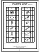
PARTS LIST Name Qty. Spare Part Name Qty MNDTHA HB A Qty. Spare Part Qty HB 8 G 1 4 M6 x15mm Cam Lock HB B HB 8 H 1 REALS102** 8 M6 x 33mm Cam Sticker HB C HB 8 I 1 4 Corner Bracket Cam Post HB D HB 8 J 1 Wood Dowel 1 Allen Wrench 5mm HB E 17 1 N 2 Wire Management Tray 4 x 16mm HB F RE WA RD A H 1 MNDTHAHB Allen Wrench 4mm Items with HB are in hardware box.
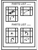
PARTS LIST Name Part K Qty. Name 1 M Part Qty. 1 Fixed Panel Top w/ Frame L MNDTHA 1 Modesty Panel PARTS LIST Name Part Qty. Name 6 Q MNRBHA Part Qty.
PARTS LIST Name Qty. Spare Part Name Qty HB R Z549 Qty. Spare Part Qty HB 2 U 1 1 Power cord 5 x 20mm HB S HB W 1 1 Controller Control box HB T 2 1 4 x 14mm NOTE: Carton Contents ①. MNDTSHA72/ MNDTSHA63 - Top, 2 Panels and 2 Wire Management trays w/ hardware. ②. MNDHA - 2 Legs with levelers. ③. Z549 - Control Box, Controller, Power Cord w/ mounting hardware.
IMPORTANT! Review ALL instructions before beginning assembly. These instructions are provided to avoid problems that may occur from improper assembly or installation. Mayline and/or its distributor are not responsible for failure resulting from improper assembly or installation of this product. Moreover, all warranties are void for failure to follow these assembly instructions. 1 install the Levelers (O) into the Legs (P and Q).
2 Insert Wood Dowels (D) and Cam Locks (A) into the Fixed Panel (M). Install Cam Posts (C) into threaded inserts in Legs (P and Q). Attach Fixed Panel (M) to Legs (P and Q) by turning Cam Locks (A). Attach Stickers (B) over Cams (A). N Q D C P A 3 B Place Top (K) upside down on a clean non-abrasive surface. Insert Wood Dowels (D) and Cam Locks (A) into the Modesty Panel (L). Install Cam Posts (C) into the Top (K). Attach Modesty Panel (L) to top by turning Cam Locks (A).
4 Install the Control Box (S) to Top (K) using Screws (R). Install the Bracket (I) to the Modesty Panel (L) and Top (K) using screws (E). S R E I L K 5 Carefully rotate the Top (K) w/ Panel and place on the Legs (P and Q).
6 Install the Top (K) to the Legs (P and Q) by Screw (H) with Wrench (J); Screws pass thru Frame into Actuator Housing on Legs. Install Memory Controller (W) in desired location on front edge of top and fasten with Screws (T). H T W 7 N G F Uninstall the Frame Mounting Screws, Qty 2, with Wrench (F). Install Wire Management Tray (N) to Frame using Screws (G) and Wrench (F). Re-install Frame Screws thru Wire Management Tray.
8 Connect Controller (W) into the correct port, and Motor Cables from Legs into Ports M1 and M2, in Control Box (S). Connect Power Cord (U) into Control Box (S). Plug Power Cord (U) into outlet and proceed with Controller Initialization on following page.
Make sure no obstacles are in the desk's path. Make sure the desktop is not touching any walls. Make sure all cords are appropriate length to accommodate the change in height. IMPORTANT: You must INITIALIZE the desk prior to first use. Controller Initialization- Press and hold the Down button on the controller until the desk reaches its lowest height, slightly raises, and stops. Release the down button, your desk is now ready for use.