
Radio User Manual

MAXX-2400HD Owner’s Manual Page 83
Controller Priority
Only one serial controller can control a given video channel at a time. In general, the first
controller to gain control of a video channel will have exclusive command. This prevents
conflicting instructions that would cause unexpected behavior. The only exception is that the
graphic user interface can immediately take control of a channel by deselecting Serial Control in
that channel’s dialog window.
External controllers are prohibited from taking control away from the GUI. The SERIAL
CONTROL mode must be checked in the channel dialog window before a remote control device
can communicate with that channel.
Configuring the Automation Interface
Setting the automation protocol for a video channel
Each video channel can be configured independently for VDCP or BVW protocol.
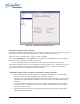
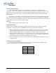
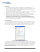
To map a protocol to a channel, Click EDIT->CONFIGURE->SERIAL PORTS from the main
pull-down menu. The screen of in Figure 34 is displayed. Use the PORT pulldown to select
COM1, 2, 3 or 4; these map to Video channels 1, 2, 3 and 4.
• Select VDCP to map the port to VDCP protocol
• Select BVW to map the port to BVW and ODETICS protocols
Note that the ODETICS protocol is layered with the BVW protocol, and that it supports clip
names of up to eight characters only. Clips with longer names will not be displayed by an Odetics
controller and will not be accessible. This includes the demo clips shipped with the server; see the
section on page 57 to rename the clips to allow their use for testing.
VDCP operation can allow control of a channel by ID number from a different numbered
serial port, while BVW and Odetics protocol control only the channel number corresponding to
the number of the serial port in use. When using both protocols, take care to not allow a VDCP
controller to address a channel that is controlled by BVW/Odetics on another serial port.
If necessary turn on “Assigned Serial Ports” in VDCP Options – this will force VDCP to control
the channel corresponding to the serial port it is connected to regardless of the channel ID in the
control messages.