
Radio User Manual

MAXX-2400HD Owner’s Manual Page 25
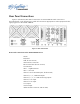
HD-SDI Video Inputs
The MAXX-2400HD records Digital video on channels 1 and 2. It has separate BNC inputs for
HD-SDI (serial digital per SMPTE 292M). HD-SDI inputs have a fixed 75-ohm termination.
HD-SDI Video Outputs
Channels 1, 2, 3 and 4 have HD-SDI video outputs per SMPTE 292M.
CVBS Monitor Outputs
Channels 1, 2, 3 and 4 have letterboxed composite video monitoring outputs.
Genlock Sync Reference
The MAXX-2400HD is designed to be referenced to an external genlock source in the form of
RS-170 black. The GENLOCK
GENLOCKGENLOCK
GENLOCK input provides a fixed 75-ohm termination. An internal crystal
reference is also provided so that the server can be used as a stand-alone player.
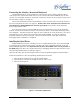
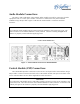
Gigabit Ethernet Port
A Gigabit Ethernet port is provided on the MAXX-2400HD. The NET 1
NET 1NET 1
NET 1 port is intended for
external transfer of program content between video servers. The NET 1
NET 1NET 1
NET 1 port is also used for remote
control using the optional Remote Workstation software. The NET 2
NET 2NET 2
NET 2 port is reserved for future use
and is not active. Use only the NET 1
NET 1NET 1
NET 1 port.
LTC Time Code Input
An LTC time code input is provided for Channel 1 and Channel 2. The LTC input provides a
>10k ohm termination. This input may be selected by means of the On-Screen user interface and
recorded as a time code reference. This input may be selected by means of the On-Screen user
interface and used as a start time reference. Note that time code is not actually recorded, the time
code read at the start of recording is captured. When the clip is played back, the time code (in
display, VITC and LTC outputs) starts from the captured time and proceeds continuously.
LTC Time Code Output
An LTC time code output is provided on the LTC OUT
LTC OUTLTC OUT
LTC OUT BNC connector. It may be selected by
means of the On-Screen user interface to output time code from any of the four video channels
during playback. The LTC output has a source impedance of <5 ohms.
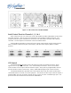
Keyboard
Attach the alphanumeric keyboard to the purple 5-pin KEYBD
KEYBDKEYBD
KEYBD connector to control the server
and manage clips with the On-Screen graphic user interface. The server will only recognize the
keyboard if it is attached before power up.
Mouse
A two-button scroll mouse is provided with the MAXX-2400HD. Plug the mouse into the
green 5-pin MOUSE
MOUSEMOUSE
MOUSE port. Do not use the USB ports, even if the supplied mouse is USB capable.
Note that the server will only recognize the mouse if it is attached before power up.
Monitor
A VESA-compliant computer monitor may be connected to the 15-pin VGA video port. The
MAXX-2400HD resolution is fixed at 1024 x 768 pixels, with a refresh rate of 72 Hz. This is best-