
Radio User Manual


Page 118 MAXX-2400HD Owner’s Manual
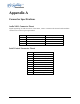
Appendix A
Connector Specifications
Audio XLR-3 Connector Pinout
Signals appearing on XLR connectors of the DXP-1, AXP-3 or AXP-4 multi-channel audio modules
conform to the following wiring standard.
Pin BALANCED ANALOG AES/EBU DIGITAL
1 SHIELD (FRAME GROUND) SHIELD (FRAME GROUND)
2 " + " OR HOT DIGITAL +
3 " – " OR COMMON DIGITAL -
SHELL FRAME GROUND FRAME GROUND
Serial Control Connector Pinout
Pin DB9-F Connector
1 GND
2 Transmit A (TX–)
3 Receive B (RX+)
4 GND
5 N/C
6 GND
7 Transmit B (TX+)
8 Receive A (RX-)
9 GND
Shell Frame ground