Tankless Electric Water Heater MS-C2PSU Series Installation and Instructions Manual Keep this Instructions Manual in a safe place once your unit is installed. You may need to refer to it for general instructions or future maintenance.
Thank you for purchasing a quality Maxwell tank-less electric water heater. To enjoy your new shower at its best, please take time to read this manual thoroughly and having done so keep it handy for future reference.
Installation of this product is restricted to indoor locations by licensed plumbing or electrical contractors only. By installing this product you acknowledge the terms of manufacturer's warranty and your authorized dealers return policy. Water heaters that have been installed cannot be returned. If you plan to install your water heater on a second floor/above ground or in a heated attic space you must follow all code requirements for installation in your area.
■ Product Features The Maxwell tank-less electric water heaters are made with multi-safety devices patented technology Additionally, the unit has the following features. 1. Tank-less, instantaneous heating on demand. No pr e-heating. No stand-by heating loss energy-saving. 2. Micro-computer control, adopting patented heating technology. Water is completely separated from electricity by multi-layers of composite nano insulation material. 3. Over-heating thermal cut-off.
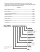
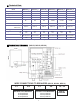
■ Technical Data Model MS80C2P_U MS100C2P_U 1 Phase Voltage/Freq V Wattage kW Max. amp.load A Min. required circuit breaker* A Min. wire size AWG cooper MS120C2P_U 1 240 V/60Hz 240 V/60Hz MS150C2P_U MS180C2P_U MS210C2P_U 1 1 1 1 240 V/60Hz 240 V/60Hz 240 V/60Hz 240 V/60Hz 12kw 15kw 18kw 21kw 8kw 10kw 34 42 50 63 75 88 45 60 60 2 X 40 2 X 50 2 X 60 8 6 6 2X8 2X8 2X8 0.53 / 2 0.53 / 2 0.53 / 2 0.85 / 3.2 Min. water flow to activate GPM / L/min. 0.85 / 3.
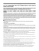
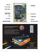
PATENTED HEATING TECHNOLOGY PATENT NO.: ZL2008 2 0081568.0 1. High temperature insulating ceramic layer. 2. Macromolecule heatconducting insulating layer. 3. High temperature heating plate. 4. Macromolecule heatconducting insulating layer. 5. High temperature insulating ceramic layer.
■ Installation Guideline The installation must be in compliance with the National Electrical Code, your local electrical and plumbing codes. 1. Make sure the appliance is intact, and the fittings are complete. 2. Please make sure the main power supply, water pressure, grounding condition, ammeter and wires meet the standard of installation requirements. 3. The appliance must be connected to properly ground dedicated branch circuits of proper voltage rating.
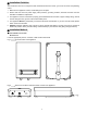
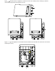
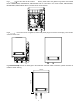
Fig 3 Remove the bracket from the appliance 3.94" 3.94" 3.94" 3.94" Fig 4 Hold the back bracket hanger in position against the wall and mark the three mounting holes. Drill three holes of 6.00mm diameter, the distance between every two holes is 100mm. (Put plastic anchor in the hole, fix the bracket on the wall. and secure the hanger using the screws supplied or an appropriate alternative method) .
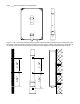
Fig 5 Uninstall screws on appliance to remove the front cover. Please pull out carefully by hand the screen row line plug before removing the front cover.
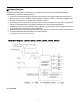
Fig 7 Connect the cable to the terminal blocks, please notice the guidance logo below the terminal blocks. MS080C2PSU, MS100C2PSU, MS120C2PSU will be connected to one circuit breaker, MS150C2PSU, MS180C2PSU, MS210C2PSU will be connected to two circuit breakers. Fig 8 Fix the front cover on appliance, before that, please plug in the screen row line plug. Then nail the screws to fix the cover.
● Water connections 1. All water pipe must comply with national and applicable state and local water pipe codes. 2. A pressure relief valve must be installed if the cold water supply pressure exceeds 150PSI (1Mpa) 3. The unit should be connected directly to the main water supply. Flush pipe with water to remove any debris or loose particles 4.
■ Trouble-shooting Problems 1. Inlet and outlet fittings leaking 2. LED no signal 3. Functional keys not working Possible Causes Corrective Actions A. Fittings not tight A. Tighten fittings. B. Rubber washer worn-out B. Change rubber washer. A. Power not connected. A. Connect power to the unit. B. LCD damaged. B. Change LCD. A. No water out from shower. A. Open valve to get water. B. Water pressure too low. B. Open valve to get pressure. C. Key or PCB damaged. C. Change key or PCB. A.
■ ACCESSORIES ½” and 3/4" water connection Ball valve For heaters with 1/2” inlet water connections for models ranging 3.3kW-, 12kW (including) For heaters with 3/4”inlet water connections for models 15 kW and over 24 inch (60cm) stainless steel, with ½” and 3/4" water connection Flexible hose For heaters with 3/4” water connections for models 15 kW and over For heaters with 1/2” water connections for models ranging 3.
■ TABLES Required Wire Gauge & Breaker Size @ 230 Volt ** * Maximum power (Amp.) based on 230 V. For 240 V application see specification table on page 4. …… ** All above breakers are of the double pole type. Warning: It is recommended to use restrictors for showers and faucets to prevent excessive water consumption.
Klimaire Products Inc.