GT804M USER MANUAL 4 CHANNEL DIGITAL VIDEO RECORDER INSTRUCTION MANUAL To obtain the best performance and ensure device function correctly, please read this instruction manual carefully and completely.
INSTRUCTION MANUAL To obtain the best performance and ensure device function correctly, please read this instruction manual carefully and completely. FCC Compliance USER-INSTALLER CAUTION: YOUR AUTHORITY TO OPERATE THIS FCC VERIFIED EQUIPMENT COULD BE VOIDED IF YOU MAKE CHANGES OR MODIFICATIONS NOT EXPRESSLY APPROVED BY THE PARTY RESPONSIBLE FOR COMPLIANCE TO PART 15 OF THE FCC RULES.
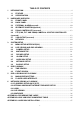
TABLE OF CONTENTS 1 2 INTRODUCTION .......................................................................................................................4 1.1 FEATURE.......................................................................................................................4 1.2 SPECIFICATION...........................................................................................................4 HARDWARE OVERVIEW ..............................................................................
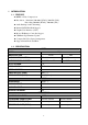
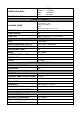
1 INTRODUCTION 1.1 FEATURE MPEG-4 Video Compression. Resolution: Real-time 720×480 ( NTSC )/ 720×576 ( PAL ) Recording 720x240 ( NTSC )/ 720x288 ( PAL ) Audio Backup / Audio Streaming. Internal SATA Hard Disk Support. Graphic User Interface ( GUI ). Mouse/ IR Remote Controller Support. USB Back Up/ Firmware Update Compact Size, Easy Space Arrangement Support Smart Phone and PDA. 1.
:2K Bytes Low Medium :4.2K Bytes High :6.2K Bytes Best :8K Bytes 12 Manual / Schedule COMPRESSION RATE RECORDING MODE PLAYBACK & SEARCH PLAYBACK SPEED Fast Forward X 2 X 8 X 16 X32 Fast Backward X32 field by field Playback Pause Slow Motion Playback X1/2 X1/4 X64 TIME SEARCH Yes EVENT SEARCH Yes EVENT LIST 3000 records per H.D.
ALARM RECORDING Yes BUZZER Yes SETUP & OTHER FUNCTIONS PASSWORD CONTROL Two levels, one for system and the other for HDD format KEY-LOCK Yes MULTI-LANGUAGE Yes FIRMWARE UPDATE USB Host OTHERS POWER INPUT DC 12V POWER CONSUMPTION (W) 17W DIMENSIONS (W x H x D) 218mm (W) × 44mm (H) × 202mm (D) WEIGHT (kg) 1.4kg OPERATION TEMPERATURE 0 - 45 ℃ ATTENTION: :A. PLEASE format the hard disk before changing the recording resolution.
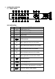
2 HARDWARE OVERVIEW 2.1 FRONT PANEL DVR OPERATION NO. ITEM 1 POWER 2 REC Recording status LED. 3 PLAY Playback status LED. 4 H.D.D 5 O H.D.D. LED. IR Sensor for remote control. 6 DVR Function Power status LED. USB connector. 7 ▲ Move upward or increase the number. 8 ▼ Move downward or decrease the number. 9 MENU Press MENU to enter or exit MENU. 10 ◄ Move leftward or decrease the number. 11 ► Move rightward or increase the number. 12 Recording button.
16 Fast Forward ×2, ×8, ×16, x32, ×64. F.Fwd 17 PLAY button & Get into Quick Time Search. PLAY 18 19 20 21 22 23 1 2 3 4 Quad Channel One Full Screen & Number: One. Channel Two Full Screen & Number: Two. Channel Three Full Screen & Number: Three. Channel Four Full Screen & Number: Four. Quad screen: All cameras are displayed. Confirmation and Backup. FRONT PANEL KEY COMBINATION Auto Swap:Press “Quad”, then press “>>” within 5 seconds. Zoom Function:Press”Enter” while in the single channel mode.
2.2 BACK PANEL NO. ITEM FUNCTION 1 MOUSE Mouse interface. 2 CAMERA IN Camera 1 video input with BNC connector. 3 CAMERA IN Camera 2 video input with BNC connector. 4 CAMERA IN Camera 3 video input with BNC connector. 5 CAMERA IN Camera 4 video input with BNC connector. 6 MONITOR OUT Video output with monitor 7 Audio IN Audio input. 8 Audio OUT Audio output. 9 Ethernet RJ-45 Ethernet network interface. 10 VGA OUT D-SUB Reserved. RS-485 Reserved. ALARM IN Reserved.
2.3 EXTERNAL ALARM(reserved) There are three types of alarms that the system can be configured, such as Motion Detection Alarm, External Alarm, and Video Loss Alarm. Motion Detection Alarm and External Alarm: When Motion Detection or External Alarm was triggered, there are 5 possible actions will be taken. a. Recording speed changed from normal to alarm recording. b.
Terminal Connectors: : T+ RS-485 sends + T- RS-485 sends - R- RS-485 receives - R+ RS-485 receives + ALARM1-4 Camera alarm input. GND GND. N.C Relay N.C. COM Relay COM N.O Relay N.O. EXAMPLE 1:Connect Alarm In One with PIR (Passive Infrared). EXAMPLE 2:Connect with Alarm Siren at Relay N.O.
2.4 IR REMOTE CONTROL(Optional) ITEM REC Press REC to start recording and press twice to stop. 1-4 Select channel 1-4 with full screen. QUAD Fast backward. Picture by picture backward. Picture by picture forward. Fast Forward. Play video forward. COPY Switch channel format. ▲ Move upward or increase the number. ► Move rightward or increase the number. ▼ Move downward or decrease the number. ◄ Move leftward or decrease the number. Enter selected items. MENU Enter or Exit Main Menu.
2.5 RS-485 CONTROLLER (reserved) PIN R+ RT+ T- RS-485 DEFINE RXDA RXDB TXDZ TXDY : Data Format: Data: 1 Byte / Parity: None / Start bit: 1 / Baud: 9600 Totally 3 bytes as follows: 1. Byte=0x10 :Broadcasting DVR Byte=0x80+ID Number :Joystick Control DVR (ID number:1~32) 2. Byte=Reference to the table as follows. :Commands of each button. 3. Byte= the 1st Byte+ the 2nd Byte : Command for confirm checksum.
user wants to connect DVR with joystick controllers, please make sure each DVR ID Number is unique.
2.7 VGA OUTPUT(reserved) VGA Output is optional. VGA output can connect with CRT or LCD monitor by D-SUB connector and the user can switch different resolutions and frequencies as follows. Resolution Frequency VGA 640×480 56Hz SVGA 800×600 60Hz XGA 1024×768 70Hz SXGA 1280×1024 75Hz 2.8 NETWORK When the DVR is turned on, it will detect the network connection automatically. If without network connection, the network function will be disabled.
3 SYSTEM SETUP 3.1 MENU SETUP INTERFACE(GUI) A. CAMERA SET E. HARD DISK SETUP B. MOTION SETUP F. NETWORK SETUP C. RECORD SETUP G.
D. ALARM SETUP H.
3.2 LIVE VIEWING AND POP-UP MENU NOTE:The pop-up menu can be activated by moving the mouse cursor to the bottom of the live viewing screen. A. GUI MENU BAR With live viewing mode, press this button to get into the GUI menu. B. DISK INFORMATION With live viewing mode, press this button to display disk information. C. DIGITAL ZOOM In the full screen mode, right-click or left-click the mouse to zoom in or zoom out the image. D. AUDIO CONTROL Press this button to turn the audio on or off。 E.
3.3 CAMERA SETUP Press ▲ or ▼ to select items. Press ◄ or ► to change values. Press SET to see more options. A. CAMERA Press ◄ or ► to switch channels. B. VIDEO ADJUST B.1 CONTRAST Press ◄ or ► to change contrast level. B.2 BRIGHTNESS Press ◄ or ► to change brightness level. B3. HUE Press ◄ or ► to change HUE level. B4. COLOR Press ◄ or ► to change color level. B5. SHAPRNESS Press ◄ or ► to change sharpness level. C. CAMERA TITLE Use mouse to select and change character.
D. DISPLAY Press ◄ or ► to change value for the corresponding camera would be displayed on the screen or not. E. AUTO SWITCH Press ◄ or ► to ON/OFF auto switch.
3.4 MOTION SETUP Press ▲ or ▼ to select items. Press ◄ or ► to change values. Press SET to see more options. A. CAMERA Press ◄ or ► to switch channels. B. MOTION DETECT Press ◄ or ► to change value for motion detect function. C. BUZZER Press ◄ or ► to change value for buzzer while motion detected. D. SENSITIVITY Press ◄ or ► to change sensitivity value from 001 (minimum) to 100 (maximum). E. AREA SETUP 1. Press SET to enter motion area setting. 2. Use mouse to select which block is needed. 3.
B. NORMAL RECORD PPS Press ◄ or ► to switch PPS in normal recording. C. ALARM RECORD PPS Press ◄ or ► to switch PPS in alarm recording. D. ALARM RECORD DURATION Press ◄ or ► to set dwell time of alarm recording. E. QUALITY Press ◄ or ► to switch quality to LOW/ MEDIUM/ HIGH/ BEST. F. RECORD MODE Press ◄ or ► to switch record mode to ALWAYS/ MOTION/ SCHEDULE / OFF. G. AUDIO RECORD Press ◄ or ► to switch AUDIO RECORD ON or OFF. H. SCHEDULE SETUP Press SET to get into schedule setup menu。 1.
A. ALARM DISPLAY MODE Press ◄ or ► to change value for ALARM DISPLAY MODE with full screen. B. VIDEO LOSS DETECT Press ◄ or ► to switch VIDEO LOSS ALARM ON or OFF. C. EVENT LOG SETUP Press SET to change value for MOTION EVENT / VIDEO LOSS EVENT to ON / OFF. D. BUZZER TIME SETUP Press SET to set dwell time of BUZZER/ ALARM. 3.7 HARD DISK SETUP Press ▲ or ▼ to select items. Press ◄ or ► to change values. Press SET to see more options. A.
D-3. FORMAT Press SET to get into FORMAT setup. Press YES or NO to execute. 3.8 NETWORK SETUP Press ▲ or ▼ to select items. Press ◄ or ► to change values. Press SET to see more options. A. IP MODE Press ▲ or ▼ to select items and ◄ or ► to change to STATIC IP or DHCP. B. HTTP PORT Press ▲ or ▼ to select items and ◄ or ► to change WEB PAGE PORT. C. IP ADDR Press ▲ or ▼ to select items and ◄ or ► to change IP ADDRESS. D. NETMASK Press ▲ or ▼ to select items and ◄ or ► to change SUBNET MASK. E.
Use mouse to setup password for ADSL account. H-4 STATE Press SET to display status of PPPoE。 I. DDNS I-1.DDNS SETTING: :Press◄ or ► to set DDNS ENABLE / DISABLE. I-2 PROVIDER: :Press◄ or ► to select DDNS provider. I-3 USER NAME: :Press SET to setup user name. I-4 PASSWORD: :Press SET to setup password. I-5 UPDATE SCHEDULE: : Use SET to dwell time of updating schedule. I-6 STATE: :Press SET to display status of DDNS。 3.
VIDEO BACKUP In multiplexer or full screen mode, press COPY to start backup and press COPY to end backup. The system will backup automatically. BACKUP FILE NAME Each backup file will be named as START TIME. EXAMPLE: 11201817.IN is Nov. 6th 18:17 AFTER BACKUP After backup, the system will copy “F4Viewer.exe” automatically on USB device for the user to play back backup file. 3.10 SYSTEM SETUP Press ▲ or ▼ to select items. Press ◄ or ► to change values. Press SET to see more options. A.
Default password: 1111. H. FIRMWARE UPDATE Press YES to start firmware update. After updated, the DVR will reboot automatically. At this moment, please do not turn off the DVR manually. NOTE: Please format USB flash memory with FAT32. I. LOAD DEFAULT Press YES to load the system default setting, and “LOAD DEFAULT!” will be displayed on the screen until recover finished. 4 DVR PLAYBACK Click the playback button on the pop-up menu.
4.2 EVENT SEARCH Double click mouse to trigger event search. Please select the event to playback。 NOTE: Display the type of the event as follows. POWER If the DVR got power loss, it will record the date and time of rebooting. RECORD If REC. button has been pressed, it will record the date and time in the event list. V.LOSS When a camera signal is lost, it will record the date, time, and corresponding channel. ALARM When ALARM is triggered, it will record the date, time, and corresponding channel.
5 DVR & USB BACKUP PLAYBACK SYSTEM REQUIREMENT: CPU: Intel Pentium III 1G or above. MEMORY: 512 MB or above. VGA: 32MB/64MB or above. OS: Microsoft Windows XP SP2 or above. VGA RESOLUTION: 1024*768 or above. 5.1 MAIN SCREEN SETTING A. MAIN SCREEN B. Open a disk drive that is with USB Backup files (e.g. F:) or other folder that is with Backup files. Each backup file will be named as START TIME. EXAMPLE: 11201817.IN is Nov.
C. Select HDD PLAY mode or FILE PLAY mode, and then open the file for playback. Open the file for Select HDD PLAY mode playback. or FILE PLAY mode 5.2 PLAYER USER INTERFACE Open the file for playback. Under HDD PLAY mode, user can use TIME/ EVENT SEARCH & COPY function 5.
A. AVI BACKUP User can save the playing video file as AVI format B.
6 NETWORK VIEWING & PLAYBACK CPU: Intel Pentium III 1G or above. Memory: 512 MB or above. VGA: 32MB/64MB or above. OS: Microsoft Windows XP SP2 or above. VGA RESOLUTION: 1024*768 or above. 6.1 IP ADDRESS SETUP ON PC SITE Install cameras inside in LAN or use network cable to connect with PC. This is for IPInstallerEng.exe to set up IP address of cameras. If OS is Windows XP SP2 or above, the following Windows Security Alert will popup. Then, please click on Unblock. Then, IPInstallerEng.
parameters. 6.2 OPTIONAL MICROSOFT INTERNET EXPLORER SETUP: OPTION 1: DISABLE ACTIVEX WARNING A. IE Tools Internet Options Security Custom Level Security Settings Download unsigned ActiveX controls Enable or Prompt (recommend). B. IE Tools Internet Options Security Custom Level Security Settings Initialize and script ActiveX controls not marked as safe Enable or Prompt (recommend).
5 Above three options are all based on select as the prompt. As indicated in the dialogue box. Please select "YES." OPTION 2: ADD TO TRUSTED SITES IE Tools Internet Options Security Trusted sites Sites 6.3 LOGIN A. INSTALL ACTIVEX B.
C. ACCOUNT & PASSWORD LOGIN After IP setup and connect to network or LAN, type IP address on IE Browser directly. The following User name & Password Login window will popup. Default user name: admin Default password: admin 6.4 LIVE VIEWING DVR Configuration Stop Fast Forward REC DVR Status System Time Screen Format Fast Backward A. DVR CONFIGURATION Get into DVR network menu. Play, Playback or Time Search B. SYSTEM TIME Live viewing mode: The current live viewing time. C.
Snapshot. D. E. Full Screen. Click again to return. F. REC. Videos are saved as AVI file. G. Playback Time Search. Click , the following Time Search….. window will popup. EVENT LIST Select a HDD to list EVENT LIST on Master or Slave HDD. Click the left button of the mouse twice to play back the selected event. TIME SEARCH Input Date and Time and click Search to play back. 6.5 CONFIGURE A.
A-1 SYSTEM INFORMATION SERVER NAME: This name will show on the IP Installer. LANUGAGE: :There are English, Traditional Chinese, and Simplified Chinese. After selecting one language, the following dialogue box will popup and ask the user to confirm. B.
highest), User, and Anonymous. Default administrator account: Username: admin Password: admin B-1 ANONYMOUS USER LOGIN: YES: Accept anonymous user login without password as guest login. NO: Anonymous login unacceptable. B-2 USER MANAGEMENT: Add: Input Username and Password and then click on Add/Set to save. Modify: Click on selected User name on User List and the following window will popup. After inputting Password and Confirm Password, click on OK.
D-1 IP ASSIGNMENT DHCP: In Dynamic Host Configuration Protocol (DHCP) mode, DHCP server will get setting done automatically. STATIC IP: Please input IP address, Subnet Mask, and Gateway based on network environment. D-2 PORT ASSIGNEMENT With IP Share (Router), the following Ports needed to be adjusted in case of conflict. E. NETWORK – PPPoE E-1 PPPoE SETTING Click on Enabled to enable ADSL dial function. Username: Username for ADSL account.
Password: Password for ADSL account. After dialed successfully, new IP address will appear. E-2 SEND MAIL AFTER DIALED Click on Enabled to enable SEND MAIL AFTER DIALED function. E-3 SUBJECT Mail subject. F. NETWORK / DDNS SETTING Click on Enabled to enable DDNS function. F-1 DYNDNS.ORG DDNS SETTING - DYNDNS.ORG PROVIDER: Select dyndns.org HOSTNAME: The registered hostname in DYNDNS.ORG. USERNAME: The registered username in DYNDNS.ORG. PASSWORD: The registered password in DYNDNS.ORG.
STATE 1. Updating: Information update. 2. Idle: Stop service. 3. DDNS registered successfully, now log by http://.ddns.camddns.com: Registered successfully. 4. Updating Failed, the name is already registered. 5. Updating Failed, please check your internet connection. F-2 DDNS.CAMNNDS.COM DDNS SETTING – DDNS.CAMDDNS.COM PROVIDER: Select ddns.camddns.com USERNAME: The registered username in DDNS.CAMDDNS.COM. SCHEDULE UPDATE: A period of time to update IP address. STATE 1.
H. EVENT SETTING H-1 MOTION DECTECTION ACTION SETTING Motion detection action can be set up on each channel individually. After the motion is detected, it will trigger emails or upload files to FTP. H-2 SUBJECT Mail Subject. H-3 INTERVAL The interval time between two emails in case the mail is sent out too frequently. I. EVENT SETTING/ ALARM SETTING I-1 EXTERNAL ALARM ACTION SETTING External alarm action can be set up on each channel individually.
J. EVENT SETTING/ MAIL & FTP J-1 MAIL & FTP SETTING Mail and FTP settings are for motion detection action and external alarm action. When both actions are detected, it will trigger emails or upload files to FTP.
APPENDIX A: RECORDING TIME LAPSE NTSC 80GB HDD PPS (Picture Per Sec.
PAL 80GB HDD PPS (Picture Per Sec.
APPENDIX B: HDD/ USB DRIVE COMPATIBLE TABLE HDD COMPATIBLE TABLE Brand Model Capacity Speed(RPM) SEAGATE ST380815AS 80G 7200 10 SEAGATE ST3160815AS 160G 7200 10 SEAGATE ST3250620AS 250G 7200 10 SEAGATE ST3400620AS 400G 7200 10 SEAGATE ST3750640AS 750G 7200 10 MAXTOR STM3250820AS 250G 7200 MAXTOR STM3250824AS 250G 7200 WD WD800AAJS-00PSA0 80G 7200 WD WD2500AAKS-00SBA0 250G 7200 WD WD4000YS-01MPB1 400G 7200 HITACHI HDS728080PLA380 82.
APPENDIX C: HARD DISK INSTALLATION 1. Hard drive jumpers need to be set properly in order to make DVR function correctly. 2. Remove DVR top cover by taking out screws from location shown below: ① ② ③ ④ 3. Below picture indicates a DVR without a H.D.D installed. 4. Please refer to the instruction from hard drive manufactory for correct jumper setting on (master) mode of the hard drive, mounting the hard drive over DVR base by facing SATA interface to DVR main board.
attached accessory pack as picture below: 5. Hooking up SATA cable and power cable to the hard drive as picture below. 6. Restores top cover then hook up with power and monitor a hard drive status message appearing if it’s been installed successful. Attentions: : 1. Hard drive master mode must be set correctly. 2. Make sure power cable is unplugged before hard drive installation starts. 3. SATA cable and power cable must be hooking up correctly.