Maxtor®Quickview 300 80/100/120/160/200/250/300GB PATA Product Manual May 24, 2005 Part Number: 000001922
May 24, 2005 Maxtor Corporation. All rights reserved. Printed in U.S.A. This publication could include technical inaccuracies or typographical errors. Changes are periodically made to the information herein – which will be incorporated in revised editions of the publication. Maxtor may make changes or improvements in the product(s) described in this publication at any time and without notice. UL/CSA/VDE/TUV/WEEE/RoHS UL standard 1954 recognition granted under File No. E78016 CSA standard C22.
Maxtor reserves the right to make changes and improvements to its products, without incurring any obligation to incorporate such changes or improvements into units previously sold or shipped. This product or document is protected by copyright and distributed under licences restricting its use, copying, distributing, and decompilation. No part of this product or document may be reproduced in any form by any means without prior written authorization of Maxtor and its licensors, if any.
Please do not remove or cover up Maxtor factory-installed drive labels. They contain information required should the drive ever need repair.Thank you for your interest in Maxtor hard disk drives. This manual provides technical information for OEM engineers and systems integrators regarding the installation and use of Maxtor hard drives. Drive repair should be performed only at an authorized repair center. For repair information, contact the Maxtor Customer Service Center at 800-2MAXTOR or 1-303-678-2015.
Table of Content Chapter 1 Introduction 1.1 1.2 1.3 1.4 1.5 MAXTOR CORPORATION ................................................................................ 1-1 AUDIENCE ............................................................................................................. 1-1 MANUAL ORGANIZATION................................................................................ 1-2 TERMINOLOGY AND CONVENTIONS ........................................................... 1-2 REFERENCES.................
Table of Contents 3.8 SYSTEM STARTUP AND OPERATION ........................................................... 3-18 Chapter 4 PRODUCT SPECIFICATIONS 4.1 Models and Capacities ............................................................................................... 4-1 4.2 Drive Configuration .................................................................................................. 4-1 4.3 Performance Specifications..............................................................................
Table of Contents Appendix A BREAKING THE 137 GIGABYTE STORAGE BARRIER 1 A.1 Breaking the 137 Gigabyte Storage Barrier ............................................................... A-1 A.1.1 History ............................................................................................................ A-1 A.1.2 Solving the 137 Gigabyte Capacity Barrier ....................................................... A-3 A.1.3 How is the Extension Implemented? .................................................
List of Figures Figure 3-1 Mechanical Dimensions of the Quickview 300 Hard Drive .......................... 3-1 Figure 3-2 20-Pack Shipping Container ......................................................................... 3-3 Figure 3-3 Jumper Locations on the PATA Interface Connector .................................... 3-4 Figure 3-4 AT Connector and Jumper Location ............................................................ 3-8 Figure 3-5 J1 DC Power and PATA Bus Combination Connector ...............
List of Tables Table 3-1 Table 3-2 Table 3-3 Table 3-4 Table 5-1 Table 5-2 AT Jumper Options .............................................................................................. 3-5 Cylinder Limitation Jumper (CLJ).......................................................................... 3-7 J1 Power Connector, Section A .......................................................................... 3-11 Logical Addressing Format .......................................................................
Chapter 1 Introduction 1.1 Maxtor Corporation Maxtor corporation is one of the world’s largest suppliers of hard disk drive products-products that help store the digital world for millions of users.
Introduction 1.3 MANUAL ORGANIZATION This manual is organized into the following chapters: • Chapter 1 – Introduction • Chapter 2 – General Description • Chapter 3 – Installation • Chapter 4 – Product Specifications • Chapter 5 – ATA Bus Interface and ATA Commands • Chapter 6 – Service and Support 1.4 TERMINOLOGY AND CONVENTIONS In the Glossary at the back of this manual, you can find definitions for many of the terms used in this manual.
Introduction • MB/s megabytes per second • MHz megahertz • ms milliseconds • MSB most significant bit • mV millivolts • ns nanoseconds • PATA Parallel ATA • PC Personal Computer • SPS Shock Protection System • tpi tracks per inch • µs microseconds • V volts The typographical and naming conventions used in this manual are listed below. Conventions that are unique to a specific table appear in the notes that follow that table.
Introduction Naming Conventions: • Host: In general, the system in which the drive resides is referred to as the host. 1.5 REFERENCES For additional information about the ATA interface, refer to the latest revision of the draft standard on the internet at http://www.t13.org/ using the link under “1410D AT Attachment - 6 with Packet Interface (ATA/ATAPI - 6)and (ATA/ATAPI -7).
Chapter 2 GENERAL DESCRIPTION This chapter summarizes the general functions and key features of the Quickview 300 80/100/120/160/200/250/300GB PATA hard disk drives, as well as the applicable standards and regulations. 2.1 PRODUCT OVERVIEW Maxtor’s Quickview 300 PATA hard disk drives are part of a family of high performance, 1-inch-high hard disk drives manufactured to meet the highest product quality standards.
General Description • Emulation of IBM® PC AT® task file register, and all AT fixed disk commands Performance • Average seek time of <9.0 ms (increased in Quiet Mode) • Average rotational latency of 4.
General Description Versatility • Quiet mode • Power saving modes • Downloadable firmware • Cable select feature • Ability to daisy-chain two drives on the interface 2.3 REGULATORY COMPLIANCE STANDARDS Maxtor Corporation’s disk drive products meet all domestic and international product safety regulatory compliance requirements. Maxtor’s disk drive products conform to the following specifically marked Product Safety Standards: • Underwriters Laboratories (UL) Standard 1950.
Chapter 3 INSTALLATION This chapter explains how to unpack, configure, mount, and connect the Maxtor Quickview 300 80/100/120/160/200/250/300GB PATA hard disk drive prior to operation. It also explains how to start up and operate the drive. 3.1 SPACE REQUIREMENTS The Quickview 300 hard disk drives are shipped without a faceplate. Figure 3-1 shows the external dimensions of the Quickview 300 PATA drives.
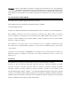
Installation 3.2 UNPACKING INSTRUCTIONS CAUTION: The maximum limits for physical shock can be exceeded if the drive is not handled properly. Special care should be taken not to bump or drop the drive. It is highly recommended that Maxtor Quickview 300 drives are not stacked or placed on any hard surface after they are unpacked. Such handling could cause media damage. 1. Open the shipping container and remove the packing assembly that contains the drive. 2. Remove the drive from the packing assembly.
Installation Figure 3-2 Quickview 300 20-Pack Shipping Container Quickview 300 80/100/120/160/200/250/300GB PATA 3-3
Installation 3.3 HARDWARE OPTIONS 3.3.1 PATA Interface Connector The configuration of a Quickview 300 PATA hard disk drive depends on the host system in which it is to be installed. This section describes the hardware options that you must take into account prior to installation.
Installation The configuration of the following three jumpers controls the drive’s five modes of operation: • CS – Cable Select • DS – Drive Select • CLJ– Cylinder Limitation Jumper • POSB - Power on standby (Remote Command) The AT PCB has two jumper locations provided to configure the drive in a system. The default configuration for the drive as shipped from the factory is with a jumper across the CS location, and open positions in the DS and CLJ positions.
Installation Master or Slave with the CS feature, the CS jumper is installed (1). The drive's position on the 80 pin conductor Ultra ATA data cable then determines whether the drive is a Master (Device 0) or a Slave (Device 1). If the drive is connected to the end of the Ultra (cable Select) data cable the drive is a Master. If the drive is connected to the middle connection it is set as a Slave.
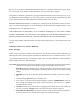
Installation 3.3.1.4 Power On Standby Upon power on, the drive will not spin up and will be in a power saving mode, irrespective of the other jumper settings. To spin up the drive, issue a Set Feature (OxEF) command with a sub-code 7. In the power saving mode, the drive will reject all other commands. Jumpers Setup Drive will spin up as normal drive and become ready in a few seconds after power up if the jumpers on pin 42 and pin 44 were not set. 3.3.1.
Installation 300GB C = 16383 H = 16 S = 63 LBA = 586,114,704 Table 3-2 Cylinder Limitation Jumper (CLJ) Figure 3-4 AT Connector and Jumper Location Pin 42 Pin 44 3-8 Quickview 300 80/100/120/160/200/250/300GB PATA
Installation 3.3.2 PATA BUS ADAPTER There are two ways you can configure a system to allow the Maxtor hard disk drives to communicate over the PATA bus of an IBM or IBMcompatible PC: 1. Connect the drive to a 40-pin PATA bus connector (if available) on the motherboard of the PC. 2. Install an IDE-compatible adapter board in the PC, and connect the drive to the adapter board. 3.3.2.
Installation Center Key Slot Pin 1 J1 IDE (40-Pin)/DC (4-Pin) Combination Connector 40-Pin IDE (J1 Section C) Pin 40 4-Pin DC Power (J1 Section A) Pin 1 4 Pin 42 3 2 Pin 44 Figure 3-5 J1 DC Power and PATA Bus Combination Connector 3-10 Quickview 300 80/100/120/160/200/250/300GB PATA 1
Installation 3.4.1 DC Power (J1, Section A) The recommended mating connectors for the +5 VDC and +12 VDC input power are listed in Table 3-3.
Installation 3.5 Mounting 3.5.1 Orientation The mounting holes on the Quickview 300 80/100/120/160/200/250/ 300GB PATA hard disk drives allow the drive to be mounted in any orientation. Figure 3-7 and Figure 3-6 show the location of the three mounting holes on each side of the drive. The drive can also be mounted using the four mounting hole locations on the PCB side of the drive.
Installation Figure 3-7 Mounting Screw Clearance for the Maxtor Quickview 300 Hard Disk Drives CAUTION: The PCB is very close to the mounting holes. Do not exceed the specified length for the mounting screws. The specified screw length allows full use of the mounting hole threads, while avoiding damaging or placing unwanted stress on the PCB. Figure 3-7 specifies the minimum clearance between the PCB and the screws in the mounting holes.
Installation 3.5.2 Clearance Clearance from the drive to any other surface (except mounting surfaces) must be a minimum of 1.25 mm (0.05 inches). 3.5.3 Ventilation The Maxtor Quickview 300 80/100/120/160/200/250/300GB PATA hard disk drives operate without a cooling fan, provided the base casting temperature as measured where the motor is attached to the base casting does not exceed 158° F (70° C). 3.5.
Installation 3.6.1.1 Connecting the Adapter Board and the Drive Use a 40-pin cable to connect the drive to the board. See figure 3-8 to connect the drive to the board: 1. Insert the 80-pin conductor cable into the mating connector of the adapter board. Make sure that pin 1 of the connector matches with pin 1 on the cable. 2. Insert the other end of the cable into the header on the drive. When inserting this end of the cable, make sure that pin 1 of the cable connects to pin 1 of the drive connector.
Installation 3.7 TECHNIQUES IN DRIVE CONFIGURATION 3.7.1 Operating system limitations Most popular operating systems available today have additional limitations which affect the use of large capacity drives. However, these limitations can not be corrected on the BIOS and it is up to the operating system manufacturers to release improved versions to address these problems.
Chapter 4 PRODUCT SPECIFICATIONS 4.1 Models and Capacities MODELS Formatted Capacity (GB LBA Mode) 6L080PO 6L100PO 6L120PO 6L160P0 6L200P0 6L250R0 6L300R0 80GB 100GB 120GB 160GB 200GB 250GB 300GB GB means 1 billion bytes. Total accessible capacity varies depending on operating environment. 4.
Product Specifications MODELS 80GB 100GB 120GB 160GB 200GB Data Zones per Surface 16 Data Sectors per Track (ID/ OD) 645/1224 Areal Density (Gbits/in2 max, ID/ OD) 75/60.8 Recording Density (kbpi, ID/OD) ID = 728 OD = 624 Track Density (ktpi) 4.3 250GB 300GB 95 ktpi Performance Specifications MODELS 80GB 100GB 120GB 160GB Seek Times (typical read, ms) Track-to-Track Average (normal seek) Full Stroke (normal seek) Average Latency (ms) 0.8 ≤ 9.0 ≤ 20.0 4.
Product Specifications MODELS 80GB 100GB 120GB 160GB 200GB 250GB 300GB Data Transfer Speed (MByte/sec max) To/From Interface (Maxtor Ultra ATA/133, up to) 133 To/From Media (ID/OD up to nn.n, where nn.n is the maximum transfer rate possible) ID = 333 OD = 619 Sustained (ID/OD up to nn.n, where nn.n is the maximum transfer rate possible) ID = 30.8 OD = 58.9 Data Buffer Size (MB)/ Type Drive Ready Time (typical sec) 4.4 8 MB 16 MB < 8.
Product Specifications 4.5 Power Requirements for 80/100/120/160/200GB (Typical) MODE 4.5.1 12V (mA) 5V (mA) POWER (W) Spin-up (peak) 1667 617 23.1 Spin-up (peak) Max 2400 1000 33.8 Seek 849 449 12.4 Read/Write 426 484 7.5 Idle 322 155 4.6 Standby 43 153 1.3 Sleep 43 153 1.3 Power Requirements for 250GB/300GB (Typical) MODE 4.5.2 12V (mA) 5V (mA) POWER (W) Spin-up (peak) 1660 632 23.1 Spin-up (peak) Max 2400 1000 33.8 Seek 997 459 14.
Product Specifications 4.6 Power Mode Definitions Spin-up The drive is spinning up following initial application of power and has not yet reached full speed. Seek A random access operation by the drive. Read/Write Data is being read from or written to the drive. Idle The drive is spinning, the actuator is parked and powered off and all other circuitry is powered on. The drive is capable of responding to read commands within 40 ms. Standby The motor is not spinning.
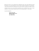
Product Specifications 4.8 Environmental Limits PARAMETER 0° C to 70° C (Base Casting) See Figure 4-1 Temperature NON-OPERATING/ STORAGE OPERATING low temperature (-40° C) high temperature (71° C) per MIL-STD-810E, method 501.3, climatic category; hot-induced conditions. Thermal Gradient 25° C per hour (maximum) Relative Humidity 5% to 95% (non-condensing) Wet Bulb 37.
Product Specifications Baseplate Temperature Measurment Location Figure 4-1 Baseplate Tempurature Measurement Location Quickview 300 80/100/120/160/200/250/300GB PATA 4-7
Product Specifications 4.9 Shock and Vibration PARAMETER OPERATING NON-OPERATING Mechanical Shock R=0.988/shock at 60 Gs; R= 0.999/shock at 30 Gs 2 msec, 1/2 sine R=0.90@>= 300G R=0.95@>= 250G R=0.99@>= 200G Rotational Shock R=0.988 @ 2000 rad/sec2 R=0.95 @ 20K rad/sec2, 1ms input R=0.90 @ 20K rad/sec2, 1ms input Rotational Random Vibration 5 - 2000 Hz 3.60 rad/sec2 RMS Overall 2 - 300 Hz 96.5 rad/sec2 RMS Random Vibration 5 - 2000 Hz 0.44 GRMS Overall PSD: 7 - 800 Hz at 3.
Product Specifications 4.10 Reliability Specifications Annualized Return Rate <1.0% Annualized Return Rate (ARR) indicates the average against products shipped. ARR includes all reasons for returns (failures, handling, damage, NDF) but does not include inventory credit returns. Start/Stop Cycles 50,000 This indicates the average minimum cycles for reliable start/ stop function. R=0.9998@ >4500, R=0.9995 @ >7500, R=0.5 @ >= 50000 Data Reliability <1 per 10e15 bits read Data errors (non-recoverable).
Product Specifications 4.11.2 Canadian Emissions Statement This digital apparatus does not exceed the Class B limits for radio noise emissions from digital apparatus as set out in the radio interference regulations of the Canadian department of communications.
Chapter 5 ATA BUS INTERFACE AND ATA COMMANDS This chapter describes the interface between the Quickview 300 hard disk drives and the PATA bus. The commands that are issued from the host to control the drive are listed, as well as the electrical and mechanical characteristics of the interface. 5.1 INTRODUCTION Maxtor Quickview 300 hard disk drives use the standard ATA/ATAPI interface. Support of various options in the standard are explained in the following sections. 5.2 MECHANICAL INTERFACE 5.2.
ATA Bus Interface and ATA Commands Hosts may assert the RESET- signal for longer than the minimum. When power is applied with RESET- asserted, the Quickview 300 disk media will not begin to spin up until RESET- is negated. This may reduce maximum current consumption for the overall system. 5.4 REGISTER ADDRESS DECODING The Quickview 300 hard disk drives allow their host systems to address the full set of command and control registers as specified in clause 7 of the ATA/ATAPI-6 standard. 5.
ATA Bus Interface and ATA Commands Table 5-1 Supported Commands Command Command Code Feature Register Value(s) FLUSH CACHE E7h IDENTIFY DRIVE ECh IDLE E3h IDLE IMMEDIATE E1h NOP 00h READ BUFFER E4h READ DMA C8h READ DMA EXT 25h READ MULTIPLE C4h READ NATIVE MAX ADDRESS F8h READ SECTOR(S) 20h READ VERIFY SECTOR(S) 40h SECURITY DISABLE PASSWORD F6h SECURITY ERASE PREPARE F3h SECURITY ERASE UNIT F4h SECURITY FREEZE LOCK F5H SECURITY SET PASSWORD F1h SECURITY UNLOCK F2h S
ATA Bus Interface and ATA Commands Table 5-1 Supported Commands Command Command Code Feature Register Value(s) SET MULTIPLE MODE C6h SLEEP E6h SMART DISABLE OPERATIONS B0h D9h SMART ENABLE OPERATIONS B0h D8h SMART ENABLE/DISABLE ATTRIBUTE AUTOSAVE B0h D2h SMART EXECUTE OFF-LINE IMMEDIATE B0h D4h SMART READ DATA B0h D0h SMART READ LOG B0h D5h SMART RETURN STATUS B0h DAh SMART SAVE ATTRIBUTE VALUES B0h D3h SMART WRITE LOG B0h D6h STANDBY E2h STANDBY IMMEDIATE E0h WRITE B
ATA Bus Interface and ATA Commands Table 5-1 Supported Commands Command WRITE SECTOR(S) Command Code Feature Register Value(s) 30h Quickview 300 80/100/120/160/200/250/300GB PATA 5-5
ATA Bus Interface and ATA Commands Identify Drive Command This command allows the host to receive parameter information from the drive. When the command is received, the drive: 1.Sets BSY 2. Stores the required parameter information in the sector buffer 3. Sets the DRQ bit 4. Generates an interrupt The host may then read the information out of the sector buffer. Parameter words in the buffer are shown in Table 5-2. Note: All reserved bits or words should be zeroes.
ATA Bus Interface and ATA Commands Table 5-2 Identify Drive Command Parameters Word CONTENT DESCRIPTION 10-19 Serial number (20 ASCII characters) 20-21 Retired 22 Reserved 23-26 Firmware revision (8 ASCII characters) 27-46 Model number (40 ASCII characters) 47 15-8: 80h 7-0: 00h = Reserved 01h-FFh: = Maximum number of sectors that shall be transferred per interrupt on READ/WRITE MULTIPLE commands 48 Reserved 49 Capabilities 15-14: Reserved for the IDENTIFY PACKET DEVICE command.
ATA Bus Interface and ATA Commands Table 5-2 Identify Drive Command Parameters Word 53 CONTENT DESCRIPTION 15-3: Reserved 2: 1 = the fields reported in word 88 are valid. 0 = the fields reported in word 88 are not valid 1: 1 = the fields reported in words (70:64) are valid.
ATA Bus Interface and ATA Commands Table 5-2 Identify Drive Command Parameters Word 67 CONTENT DESCRIPTION Minimum PIO transfer cycle time without flow control 15-0: 68 Cycle time in nanoseconds Minimum PIO transfer cycle time with IORDY flow control 15-0: Cycle time in nanoseconds 69-70 Reserved (for future command overlap and queuing) 71-74 Reserved for IDENTIFY PACKET DEVICE command.
ATA Bus Interface and ATA Commands Table 5-2 Identify Drive Command Parameters Word 81 CONTENT DESCRIPTION Minor version number 0000h or FFFFh = device does not report version. 0001h-FFFEh = see 6.16.41 of ATA/ATAPI-7 specification 82 Command set supported.
ATA Bus Interface and ATA Commands Table 5-2 Identify Drive Command Parameters Word 83 84 85 CONTENT DESCRIPTION 7: See Address Offset Reserved Area Boot, INCITS TR27:2001 6: 1 = SET FEATURES subcommand required to spinup after power-up 5: 1 = Power-Up In Standby feature set supported 4: 1 = Removable Media Status Notification feature set supported 3: 1 = Advanced Power Management feature set supported 2: 1 = CFA feature set supported 1: 1 = READ/WRITE DMA QUEUED supported 0: 1 = DOWNLOAD
ATA Bus Interface and ATA Commands Table 5-2 Identify Drive Command Parameters Word 85 86 87 CONTENT DESCRIPTION 7: 1 = release interrupt enabled 6: 1 = look-ahead enabled 5: 1 = write cache enabled 4: Shall be cleared to zero to indicate that the PACKET Command feature set is not supported. 3: 1 = Power Management feature set enabled 2: 1 = Removable Media feature set enabled 1: 1 = Security Mode feature set enabled 0: 1 = SMART feature set enabled Command set/feature enabled.
ATA Bus Interface and ATA Commands Table 5-2 Identify Drive Command Parameters Word 87 88 CONTENT DESCRIPTION 6: 1 = WRITE DMA FUA EXT and WRITE MULTIPLE FUA EXT commands supported 5: General Purpose Logging feature set supported 4: 1 = Valid CONFIGURE STREAM command has been executed 3: 1 = Media Card Pass Through Command feature set enabled 2: 1 = Media serial number is valid 1: 1 = SMART self-test supported 0: 1 = SMART error logging supported 15: Reserved 14: 1 = Ultra DMA mode 6 is
ATA Bus Interface and ATA Commands Table 5-2 Identify Drive Command Parameters Word 93 CONTENT DESCRIPTION Hardware reset result. The contents of bits (12:0) of this word shall change only during the execution of a hardware reset 15: Shall be cleared to zero. 14: Shall be set to one. 13: 1 = device detected CBLID- above ViH. 0 = device detected CBLID- below ViL 12-8: Device 1 hardware reset result. Device 0 shall clear these bits to zero. Device shall set these bits as follows: 12: Reserved.
ATA Bus Interface and ATA Commands Table 5-2 Identify Drive Command Parameters Word 94 CONTENT DESCRIPTION 15-8: Vendor’s recommended acoustic management value. 7-0: Current automatic acoustic management value 95 Stream Minimum Request Size 96 Stream Transfer Time - DMA/PIO 97 Stream Access Latency - DMA 98-99 100-103 Streaming Performance Granularity Maximum user LBA for 48-bit Address feature set.
ATA Bus Interface and ATA Commands Table 5-2 Identify Drive Command Parameters Word 128 CONTENT DESCRIPTION Security status 15-9: Reserved 8: Security level 0 = High, 1 = Maximum 7-6: Reserved 5: 1 = Enhanced security erase supported 4: 1 = Security count expired 3: 1 = Security frozen 2: 1 = Security locked 1: 1 = Security enabled 0: 1 = Security supported 129-159 Vendor specific 160-254 Reserved 255 Integrity word 15-8: Checksum 7-0: Signature 5-16 Quickview 300 80/100/120/160
Chapter 6 SERVICE AND SUPPORT 6.1 Product Support/Technical Assistance/Customer Service For Product Service and Support Information please visit our site at: www.maxtor.com for warranty service or www.maxtorkb.com for technical support.
Appendix A BREAKING THE 137 GIGABYTE STORAGE BARRIER This appendix provides information about the 137GB storage barrier. It discusses the history, cause and the solution to overcome this barrier. A.1 Breaking the 137 Gigabyte Storage Barrier Capacity barriers have been a fact of the personal computer world since its beginnings in the early 1980’s. At least 10 different capacity barriers have occurred in the storage industry over the last 15 years.
Breaking the 137GB Storage Barrier of the hard disk was accessible. This inability to access the entire drive is referred to as a “capacity barrier” and it has been seen and overcome many times in the computer and disk drive industry. The 137-gigabyte barrier is the result of the original design specification for the ATA interface that provided only 28 bits of address for data.
Breaking the 137GB Storage Barrier A.1.2 Solving the 137 Gigabyte Capacity Barrier As described earlier, the issue causing the 137-gigabyte barrier is the 28bit addressing method of the original ATA specification. A change to expand this method was required to provide more address bits for the interface, allowing significant growth for many years to come. A critical issue in expanding the addressing capability was maintaining compatibility with the existing installed base of products.
Breaking the 137GB Storage Barrier A.1.5 What Else is Involved? Effort is required from OS vendors to increase storage device addressing up to 48 bits or more. This increase will be a significant challenge for many OS vendors that have 32-bit code models. Adapting to 48-bit commands will be easy, but most vendors will stop filling data at the 32bit boundary and pad the upper 16 bits with zeros, leaving that space empty.
Breaking the 137GB Storage Barrier Appendix B: Big Numbers • 131 kilobytes = 131,000 bytes a little more than 30 pages of text • 33 megabytes = 33,000,000 bytes more than 8,000 pages of text or 25 300-page books • 137 gigabytes = 137,000,000,000 bytes more than 100,000 books, or the contents of a good library • 2.
GLOSSARY B A ACCESS – (v) Read, write, or update information on some storage medium, such as a disk. (n) One of these operations. ACCESS TIME – The interval between the time a request for data is made by the system and the time the data is available from the drive. Access time includes the actual seek time, rotational latency, and command processing overhead time. See also seek, rotational latency, and overhead. ACTUATOR – Also known as the positioner.
Glossary BPI – Abbreviation for bits per inch. A measure of how densely information is packed on a storage medium. Flux changes per inch is also a term commonly used in describing storage density on a magnetic surface. BUFFER – An area of RAM reserved for temporary storage of data that is waiting to be sent to a device that is not yet ready to receive it. The data is usually on its way to or from the disk drive or some other peripheral device.
Glossary DISK CONTROLLER – A plug-in board, or embedded circuitry on the drive, that passes information to and from the disk. The Maxtor disk drives all have controllers embedded on the drive printed-circuit board. DISKWARE – The program instructions and data stored on the disk for use by a processor. DMA – Acronym for direct memory access.
Glossary G GIGABYTE (GB) – One billion bytes (one thousand megabytes). GUIDE RAILS – Plastic strips attached to the sides of a disk drive mounted in an IBM AT and compatible computers so that the drive easily slides into place. H HALF HEIGHT – Term used to describe a drive that occupies half the vertical space of the original full size 5 1/4-inch drive. 1.625 inches high.
Glossary K M KILOBYTE (Kb) – A unit of measure consisting of 1,024 (210) bytes. L LANDING ZONE – A position inside the disk’s inner cylinder in a non data area reserved as a place to rest the heads during the time that power is off. Using this area prevents the heads from touching the surface in data areas upon power down, adding to the data integrity and reliability of the disk drive.
Glossary MTTR – Mean Time To Repair. The average time it takes to repair a drive that has failed for some reason. This only takes into consideration the changing of the major sub-assemblies such as circuit board or sealed housing. Component level repair is not included in this number as this type of repair is not performed in the field. O OVERHEAD – The processing time of a command by the controller, host adapter or drive prior to any actual disk accesses taking place.
Glossary REMOVABLE DISK – Generally said of disk drives where the disk itself is meant to be removed, and in particular of hard disks using disks mounted in cartridges. Their advantage is that multiple disks can be used to increase the amount of stored material, and that once removed, the disk can be stored away to prevent unauthorized use. RLL – Run Length Limited. A method used on some hard disks to encode data into magnetic pulses.
Glossary SUBSTRATE – The material the disk platter is made of beneath the magnetic coating. Hard disks are generally made of aluminum or magnesium alloy (or glass, for optical disks) while the substrate of floppies is usually mylar. SURFACE – The top or bottom side of the platter which is coated with the magnetic material for recording data. On some drives one surface may be reserved for positioning information. U UNFORMATTED CAPACITY – The total number of bytes of data that could be fit onto a disk.
INDEX A J abbreviations 1-1 adapter board 2-4, 3-20 jumper configurations 3-6 jumper locations 3-5 jumper options 3-6 C cable Select 3-7 cable select (CS) jumper 3-6 clearance 3-19 command descriptions 5-2 connector, IDE 3-11, 3-16 cooling fan requirements 3-19 D daisy-chain 2-3 daisy-chained 3-6 drive select (DS) jumper 3-7 M maximum screw torque 3-18 mechanical dimensions 3-1 motherboard 3-20 mounting 3-17 mounting dimensions 3-17 mounting holes 3-17 mounting screw clearance 3-18 mounting screws 3-1