Maxtor Fireball3 November 21 2003 Part Number: 000001836
© November 21 2003 Maxtor Corporation. All rights reserved. Printed in U.S.A. This publication could include technical inaccuracies or typographical errors. Changes are periodically made to the information herein – which will be incorporated in revised editions of the publication. Maxtor may make changes or improvements in the product(s) described in this publication at any time and without notice. Maxtor , MaxFax are registered trademarks of Maxtor Corporation, registered in the U.S.A.
Before You Begin Thank you for your interest in Maxtor hard disk drives. This manual provides technical information for OEM engineers and systems integrators regarding the installation and use of Maxtor hard drives. Drive repair should be performed only at an authorized repair center. For repair information, contact the Maxtor Product Support Center at 1-800-2MAXTOR. CAUTION: Maxtor hard drives are precision products.
Table of Contents Chapter 1 INTRODUCTION 1.1 1.2 1.3 1.4 Maxtor Corporation .................................................................................................. Manual Organization................................................................................................. Abbreviations ............................................................................................................ Conventions....................................................................................
Table of Contents Chapter 4 HANDLING AND INSTALLATION 4.1 4.2 4.3 4.4 4.5 Hard Drive Handling Precautions .............................................................................. Electro-Static Discharge (ESD) .................................................................................. Unpacking and Inspection ......................................................................................... Repacking ......................................................................................
List of Figures Figure 2-1 Figure 3-1 Figure 4-1 Figure 4-2 viii PCBA Jumper Location and Configuration ................................................... 2-6 Outline and Mounting Dimensions .............................................................. 3-3 Single-Pack Shipping Container ................................................................... 4-2 25-Pack Shipping Container .........................................................................
Chapter 1 INTRODUCTION 1.1 Maxtor Corporation Maxtor Corporation has been providing high-quality computer storage products since 1982. Along the way, we’ve seen many changes in data storage needs. Not long ago, only a handful of specific users needed more than a couple hundred megabytes of storage. Today, downloading from the Internet and CD-ROMs, multimedia, networking and advanced office applications are driving storage needs even higher.
Introduction 1.
Introduction Signal Conventions Signal names are shown in all uppercase type. All signals are either high active or low active signals. A dash character (-) at the end of a signal name indicates that the signal is low active. A low active signal is true when it is below ViL and is false when it is above ViH. A signal without a dash at the end indicates that the signal is high active. A high active signal is true when it is above ViH and is false when it is below ViL.
Chapter 2 PRODUCT DESCRIPTION 2.1 Product Description The Fireball 3 is the industries first 40Gb single-head/single platter hard drive with an Ultra ATA/133 interface. Combining value and performance, this is an excellent choice for entry-level desktop systems and consumer electronic applications. The Maxtor Fireball 3 drive is the latest in the family of Maxtor single platter 5400RPM drives designed for higher reliability.
Product Description • 5400 RPM spin speed • 12.
Product Description Sector Address Translation All Maxtor hard drives feature a universal translate mode. In an AT/EISA-class system, the drive may be configured to any specified combination of cylinders, heads and sectors (within the range of the drive's formatted capacity).
Product Description Software ECC Correction 24 symbols, single burst, guaranteed 2.4 Cache Management Buffer Segmentation The data buffer is organized into two segments: the data buffer and the micro controller scratch pad. The data buffer is dynamically allocated for read and write data depending on the commands received. A variable number of read and write buffers may exist at the same time. Read-Ahead Mode Normally, this mode is active.
Product Description Read/Write Electronics An integrated circuit mounted within the sealed head disk assembly (near the read/ write heads) provides up to eight head selection depending on the model. It also provides read pre-amplification and write drive circuitry. Read/Write Heads and Media Low mass, low force giant magneto-resistive read/write heads record data on 3.5inch diameter disks. Maxtor uses a sputtered thin film medium on all disks for Maxtor hard drives.
Product Description depends on the type of command and which drive is selected. Only the drive selected executes the command and activates the data bus in response to host I/O reads; the drive not selected remains inactive. A master/slave relationship exists between the two drives: device 0 is the master and device 1 the slave. When the Master is closed (factory default, figure 2-1), the drive assumes the role of master; when open, the drive acts as a slave.
Product Description JUMPER CONFIGURATION Master/Slave Only drive in single drive system* Master drive in dual drive system* Slave drive in dual drive system J49 J50 J43 J44 J41 J42 O O O C Cylinder Limitation Disabled* Enabled O C Factory Reserved 2.
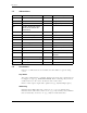
Chapter 3 PRODUCT SPECIFICATIONS 3.1 Models and Capacities MODELS Formatted Capacity (GB LBA Mode) 2F020J0/L0 2F030J0/L0 2F040J0/L0 20GB 30GB 40GB GB means 1 billion bytes. Total accessible capacity varies depending on operating environment. 3.
Product Specifications 3.3 Performance Specifications MODELS 20GB 30GB Seek Times (typical read, ms) Track-to-Track 1.0 ≤12.0 Average (normal seek) Full Stroke (normal seek) ≤23 Average Latency (ms) 5.55 Controller Overhead (ms) <0.3 Rotation Speed (RPM ±0.1%) 5400 Data Transfer Speed (MByte/sec max) To/From Interface (Maxtor Ultra ATA/133, up to) 133 To/From Media (ID/OD up to nn.n, where nn.
Product Specifications 17 ±0.7 6.35 ±0.25 Pin 1 28.5 ±0.5 41.28 ±0.5 3.18 ±0.25 41.61 ±0.25 101.60 ±0.25 44.45 ±0.25 Pin 1 95.25 ±0.25 101.6 ±0.5 70.82 5.77 5.91 146.1 ±0.
Product Specifications 3.5 Power Requirements MODE 12V (MA) 5V (MA) POWER (W) 1687.75 552.76 23.02 448.6 340.68 7.09 Read/Write 329.10 453.76 6.22 Idle 257.65 350.73 4.2 Standby 36.23 111.71 0.99 Sleep 36.23 110.88 0.99 Spin-up (peak) Seek 3.6 Power Mode Definitions Spin-up The drive is spinning up following initial application of power and has not yet reached full speed. Seek A random access operation by the drive. Read/Write Data is being read from or written to the drive.
Product Specifications 3.8 Environmental Limits PARAMETER NON-OPERATING/ STORAGE OPERATING 5° C to 55° C (with no ARR impact) 0° C to 60° C (margin demonstrated1) Temperature Low temperature (-40° C) High temperature (71° C) per MIL-STD-810E, method 501.3, climatic category; hot-induced conditions.
Product Specifications 3.9 Shock and Vibration PARAMETER OPERATING NON-OPERATING Mechanical Shock R>=0.988/shock at 60 Gs; R>0.999/shock at 30 Gs 2 msec, 1/2 sine R=0.90@>= 300G 1 disk R=0.95@>= 250G, 1 disk R=0.99@>= 200G, 1 disk Rotational Shock R>-0.988 @ 2000 rad/sec2 R>- 0.95 @ 20K rad/sec2, 0.5ms to 1ms input R>- 0.99 @ 15K rad/sec2, 0.5ms to 1ms input Rotational Random Vibration 5 - 2000 Hz 4.70 rad/sec2 RMS Overall 2 - 300 Hz 96.5 rad/sec2 RMS Random Vibration 5 - 2000 Hz 0.
Product Specifications 3.10 Reliability Specifications Annualized Return Rate <1.0% Annualized Return Rate (ARR) indicates the average against products shipped. ARR includes all reasons for returns (failures, handling, damage, NDF) but does not include inventory credit returns. Load/Unload Cycles 100,000 This indicates the average minimum cycles for reliable load/unload function. Data Reliability <1 per 10e15 bits read Data errors (non-recoverable).
Product Specifications 3.12 Safety Regulatory Compliance All Maxtor hard drives comply with relevant product safety standards such as CE, CUL, TUV and UL rules and regulations. As delivered, Maxtor hard drives are designed for system integration before they are used.
Chapter 4 HANDLING AND INSTALLATION 4.1 Hard Drive Handling Precautions • If the handling precautions are not followed, damage to the hard drive may result whichmay void the warranty. • During handling, NEVER drop, jar, or bump a drive. Handle the drive by its sides and avoid touching the printed circuit board assembly (PCBA). • Hard drives are sensitive to electrostatic discharge (ESD) damage. Use proper ESD practices by grounding yourself and the computer system the hard drive will be installed in.
Handling and Installation 4.3 Unpacking and Inspection Retain any packing material for reuse. Inspect the shipping container for evidence of damage in transit. Notify the carrier immediately in case of damage to the shipping container. As they are removed, inspect drives for evidence of shipping damage or loose hardware. If a drive is damaged (and no container damage is evident), notify Maxtor immediately for drive disposition.
Handling and Installation Figure 4-2 25-Pack Shipping Container Maxtor Fireball3 4-3
Handling and Installation 4.4 Repacking If a Maxtor drive requires return, repack it using Maxtor packing materials, including the antistatic bag. 4.5 Physical Installation The Maxtor hard drive design allows greater shock tolerance than that afforded by larger, heavier drives. The drive may be mounted in any attitude using four size 6-32 screws with 3 mm maximum penetration and a maximum torque of 5-inch pounds. Allow adequate ventilation to the drive to ensure reliable operation.
Chapter 5 ATA BUS INTERFACE AND ATA COMMANDS This chapter describes the interface between Maxtor Fireball3 hard disk drives and the ATA bus. The commands that are issued from the host to control the drive are listed, as well as the electrical and mechanical characteristics of the interface. 5.1 INTRODUCTION Maxtor Fireball3 hard disk drives use the standard ATA/ATAPI interface. Support of various options in the standard are explained in the following sections. 5.2 MECHANICAL INTERFACE 5.2.
ATA Bus Interface and ATA Commands 5.4 REGISTER ADDRESS DECODING The Maxtor Fireball3 hard disk drives allow their host systems to address the full set of command and control registers as specified in clause 7 of the ATA/ATAPI-6 standard. 5.5 COMMAND INTERFACE 5.5.1 General Feature Set The µProcessor, Disk Controller, and ATA Interface electronics are contained in a proprietary ASIC developed by Maxtor. 5.5.
ATA Bus Interface and ATA Commands Table 5-1 Supported Commands Command Command Code Feature Register Value(s) READ BUFFER E4h READ DMA C8h, C9h READ LONG 22h, 23h READ MULTIPLE C4h READ NATIVE MAX ADDRESS F8h READ SECTOR(S) 20h, 21h READ VERIFY SECTOR(S) 40h, 41h SECURITY DISABLE PASSWORD F6h SECURITY ERASE PREPARE F3h SECURITY ERASE UNIT F4h SECURITY FREEZE LOCK F5H SECURITY SET PASSWORD F1h SECURITY UNLOCK F2h SEEK 70h SET FEATURES EFh Note 1 SET MAX ADDRESS F9h 00h
ATA Bus Interface and ATA Commands Table 5-1 Supported Commands Command Command Code Feature Register Value(s) SMART EXECUTE OFF-LINE IMMEDIATE B0h D4h SMART READ DATA B0h D0h SMART READ LOG B0h D5h SMART RETURN STATUS B0h DAh SMART SAVE ATTRIBUTE VALUES B0h D3h SMART WRITE LOG B0h D6h STANDBY 96h, E2h STANDBY IMMEDIATE 94h, E0h WRITE BUFFER E8h WRITE DMA CAh, CBh WRITE MULTIPLE C5h WRITE PIO OVERLAP 34h WRITE SECTOR(S) 30h, 31h Note: 1.
ATA Bus Interface and ATA Commands Identify Drive Command This command allows the host to receive parameter information from the drive. When the command is received, the drive: 1. Sets BSY 2. Stores the required parameter information in the sector buffer 3. Sets the DRQ bit 4. Generates an interrupt The host may then read the information out of the sector buffer. Parameter words in the buffer are shown in Table 5-2. Note: All reserved bits or words should be zeroes.
ATA Bus Interface and ATA Commands Table 5-2 Identify Drive Command Parameters Word 20-21 22 CONTENT DESCRIPTION Retired Obsolete 23-26 Firmware revision (8 ASCII characters) 27-46 Model number (40 ASCII characters) 47 15-8: 80h 7-0: 00h = Reserved 01h-FFh: = Maximum number of sectors that shall be transferred per interrupt on READ/WRITE MULTIPLE commands 48 Reserved 49 Capabilities 15-14: Reserved for the IDENTIFY PACKET DEVICE command.
ATA Bus Interface and ATA Commands Table 5-2 Identify Drive Command Parameters Word 53 CONTENT DESCRIPTION 15-3: Reserved 2: 1 = the fields reported in word 88 are valid. 0 = the fields reported in word 88 are not valid 1: 1 = the fields reported in words (70:64) are valid.
ATA Bus Interface and ATA Commands Table 5-2 Identify Drive Command Parameters Word 67 CONTENT DESCRIPTION Minimum PIO transfer cycle time without flow control 15-0: 68 Cycle time in nanoseconds Minimum PIO transfer cycle time with IORDY flow control 15-0: Cycle time in nanoseconds 69-70 Reserved (for future command overlap and queuing) 71-74 Reserved for IDENTIFY PACKET DEVICE command.
ATA Bus Interface and ATA Commands Table 5-2 Identify Drive Command Parameters Word 81 CONTENT DESCRIPTION Minor version number 0000h or FFFFh = device does not report version. 0001h-FFFEh = see 6.16.41 of ATA/ATAPI-7 specification 82 Command set supported.
ATA Bus Interface and ATA Commands Table 5-2 Identify Drive Command Parameters Word 83 84 85 CONTENT DESCRIPTION 7: See Address Offset Reserved Area Boot, INCITS TR27:2001 6: 1 = SET FEATURES subcommand required to spinup after power-up 5: 1 = Power-Up In Standby feature set supported 4: 1 = Removable Media Status Notification feature set supported 3: 1 = Advanced Power Management feature set supported 2: 1 = CFA feature set supported 1: 1 = READ/WRITE DMA QUEUED supported 0: 1 = DOWNLOAD
ATA Bus Interface and ATA Commands Table 5-2 Identify Drive Command Parameters Word 85 86 87 CONTENT DESCRIPTION 7: 1 = release interrupt enabled 6: 1 = look-ahead enabled 5: 1 = write cache enabled 4: Shall be cleared to zero to indicate that the PACKET Command feature set is not supported. 3: 1 = Power Management feature set enabled 2: 1 = Removable Media feature set enabled 1: 1 = Security Mode feature set enabled 0: 1 = SMART feature set enabled Command set/feature enabled.
ATA Bus Interface and ATA Commands Table 5-2 Identify Drive Command Parameters Word 87 88 CONTENT DESCRIPTION 6: 1 = WRITE DMA FUA EXT and WRITE MULTIPLE FUA EXT commands supported 5: General Purpose Logging feature set supported 4: 1 = Valid CONFIGURE STREAM command has been executed 3: 1 = Media Card Pass Through Command feature set enabled 2: 1 = Media serial number is valid 1: 1 = SMART self-test supported 0: 1 = SMART error logging supported 15: Reserved 14: 1 = Ultra DMA mode 6 is
ATA Bus Interface and ATA Commands Table 5-2 Identify Drive Command Parameters Word 93 CONTENT DESCRIPTION Hardware reset result. The contents of bits (12:0) of this word shall change only during the execution of a hardware reset 15: Shall be cleared to zero. 14: Shall be set to one. 13: 1 = device detected CBLID- above ViH. 0 = device detected CBLID- below ViL 12-8: Device 1 hardware reset result. Device 0 shall clear these bits to zero. Device shall set these bits as follows: 12: Reserved.
ATA Bus Interface and ATA Commands Table 5-2 Identify Drive Command Parameters Word 94 CONTENT DESCRIPTION 15-8: Vendor’s recommended acoustic management value. 7-0: Current automatic acoustic management value 95 Stream Minimum Request Size 96 Stream Transfer Time - DMA 97 Stream Access Latency - DMA 98-99 100-103 Streaming Performance Granularity Maximum user LBA for 48-bit Address feature set.
ATA Bus Interface and ATA Commands Table 5-2 Identify Drive Command Parameters Word 128 129-159 160 CONTENT DESCRIPTION Security status 15-9: Reserved 8: Security level 0 = High, 1 = Maximum 7-6: Reserved 5: 1 = Enhanced security erase supported 4: 1 = Security count expired 3: 1 = Security frozen 2: 1 = Security locked 1: 1 = Security enabled 0: 1 = Security supported Vendor specific CFA power mode 1 15: Word 160 supported 14: Reserved 13: CFA power mode 1 is required for one or m
Chapter 6 SERVICE AND SUPPORT 6.1 Product Support/Technical Assistance/Customer Service For Product Service and Support Information please visit our site at: www.maxtor.com for warranty service or www.maxtorkb.com for technical support.
GLOSSARY A ACCESS – (v) Read, write, or update information on some storage medium, such as a disk. (n) One of these operations. ACCESS TIME – The interval between the time a request for data is made by the system and the time the data is available from the drive. Access time includes the actual seek time, rotational latency, and command processing overhead time. See also seek, rotational latency, and overhead. ACTUATOR – Also known as the positioner.
Glossary also a term commonly used in describing storage density on a magnetic surface. BUFFER – An area of RAM reserved for temporary storage of data that is waiting to be sent to a device that is not yet ready to receive it. The data is usually on its way to or from the disk drive or some other peripheral device. BUS – The part of a chip, circuit board, or interface designed to send and receive data. BYTE – The basic unit of computer memory, large enough to hold one character of alphanumeric data.
Glossary DISKWARE – The program instructions and data stored on the disk for use by a processor. DMA – Acronym for direct memory access. A process by which data moves directly between a disk drive (or other device) and system memory without passing through the CPU, thus allowing the system to continue processing other tasks while the new data is being retrieved. DRIVE – Short form of disk drive.
Glossary H HALF HEIGHT – Term used to describe a drive that occupies half the vertical space of the original full size 5 1/4-inch drive. 1.625 inches high. HARD DISK – A type of storage medium that retains data as magnetic patterns on a rigid disk, usually made of an iron oxide or alloy over a magnesium or aluminum platter. Because hard disks spin more rapidly than floppy disks, and the head flies closer to the disk, hard disks can transfer data faster and store more in the same volume.
Glossary M LATENCY – The period of time during which the read/write heads are waiting for the data to rotate into position so that it can be accessed. Based on a disk rotation speed of 3,662 rpm, the maximum latency time is 16.4 milliseconds, and the average latency time is 8.2 milliseconds. LOGICAL FORMAT – The logical drive geometry that appears to an AT system BIOS as defined by the drive tables and stored in CMOS.
Glossary MTTR – Mean Time To Repair. The average time it takes to repair a drive that has failed for some reason. This only takes into consideration the changing of the major sub-assemblies such as circuit board or sealed housing. Component level repair is not included in this number as this type of repair is not performed in the field. N NANOSECOND (ns)– One billionth of a second (0.000000001 second).
Glossary RAM DISK – A “phantom disk drive” for which a section of system memory (RAM) is set aside to hold data, just as if it were a number of disk sectors. The access to this data is extremely fast but is lost when the system is reset or turned off. READ AFTER WRITE – A mode of operation that has the computer read back each sector on the disk, checking that the data read back is the same as recorded. This slows disk operations, but raises reliability.
Glossary SPINDLE – The center shaft of the disk upon which the drive’s platters are mounted. SPUTTER – A type of coating process used to apply the magnetic coating to some high-performance disks. In sputtering, the disks are placed in a vacuum chamber and the coating is vaporized and deposited on the disks. The resulting surface is hard, smooth, and capable of storing data at high density. Maxtor disk drives use sputtered thin film disks.
Glossary UNFORMATTED CAPACITY – The total number of bytes of data that could be fit onto a disk. Formatting the disk requires some of this space to record location, boundary definitions, and timing information. After formatting, user data can be stored on the remaining disk space, known as formatted capacity. The size of a Maxtor drive is expressed in formatted capacity. V VOICE COIL – A type of motor used to move the disk read/write head in and out to the right track.
INDEX A J abbreviations 1-2 automatic write reallocation 2-4 air filtration system 2-5 ATA bus interface and ATA commands, 5-1 jumper configurations 2-7 jumper locations 2-6 L logical addressing addressing 2-3 C cable Select option 2-6 cable select (CS) jumper 2-7 clearance 3-3 command descriptions 5-2 cylinder limitation jumper description 2-7 M mechanical dimensions 3-3 mounting 3-3 mounting dimensions 3-3 mounting holes 3-30 D O drive configuration 3-1 outline and mounting dimensions 3-3 E P
INDEX S sector address translations 2-3 shipping container 4-2,4-3 slave Present 2-5 slave present (SP) jumper 2-5 space requirements, 3-3 signal conventions 1-3 shock and vibration 3-6 signal cable and connector 5-1 service and support 6-1 supported commands 5-1 T terminology and conventions, 1-2 U unpacking and inspection, 4-2 V ventilation, 2-5 Maxtor DiamondMax Plus8 20/30/40GB AT I-2